


Technical Reference Guide
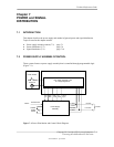
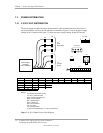
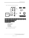
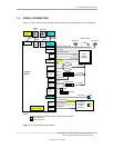
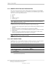
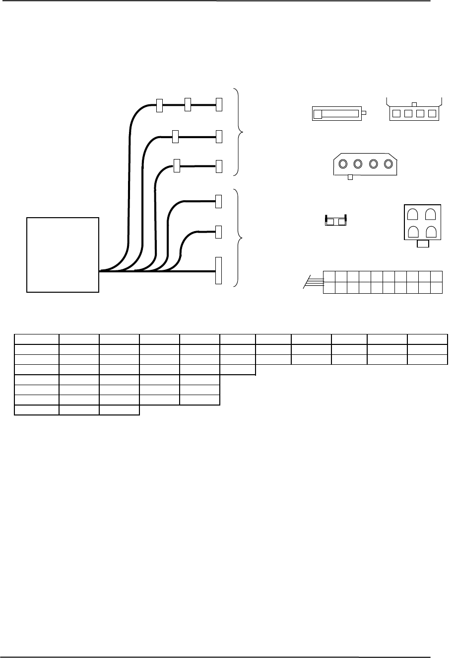
Figure 7-3 shows the power supply cabling for the d325 model.
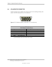
Pin 2 Pin 8 Pin 9 Pin 10
(Assy
P7, P8
4 3 2 1
P4, P5
4 5
1 2 3
P1
1
12
2
5
4
3
7
6
10
13
8
9
14
15
16
17
18
19
20
11
1 2
4 3
1 2 3 4
1
2
P9
P2, P4-6, P10
P3
To
Drive
Assemblies
P1
P8
System
Board
P7
P6
P5
P3
P9
P4
P2
P10
To
Power Supply
Assembly
. #308437)
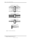
Conn. Pin 1 Pin 3 Pin 4 Pin 5 Pin 6 Pin 7
P1 +3.3 +3.3 RTN +5 RTN POK +5 ux +12 +5 RTN A
P1 [1] +3.3 -12 RTN
P4, 5 +3.3 RTN +5 RTN
P6, 10 +12 GND GND +5
P3 GND GND
RTN
+12
PS On RTN RTN NC +5 +5
+12.8 +12.8
GND GND +12 P7, +5 8
P9 C FC N
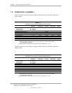
NOTES:
DC
.
ground)
nd
FC = Fan Command
or P1
igure 7-3. d325 Model Power Cable Diagram
Connectors not shown to scale.
All + and - values are V
RTN = Return (sig
GND = Power grou
nal
RS = Remote sense
POK = Power OK
NC = Not connected
[1] This row represents pins 11 - 20 of connect
F
Compaq D315 and hp d325 Personal Computers
Featuring the AMD Athlon XP Processor
Second Edition - April 2003
7-7