


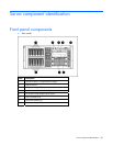
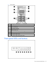
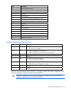
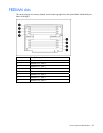

Server component identification 85
Item Description
12 Memory board connector 1
13 Memory board connector 2
14 PPM 1
15 Processor 1
16 Power connector
17 Fan control/HP Systems Insight Display connector
18 USB tape drive connector
19 IDE connector
20 Processor 2
21 PPM 2
22 Power connector
23 Front video connector
24 Internal USB connector
25 Serial 2 connector
26 Parallel connector
27 Diskette drive connector
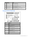
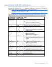
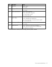
System maintenance switch
Position Default Function
S1 Off Off = iLO 2 security is enabled.
On = iLO 2 security is disabled.
S2 Off Off = System configuration can be modified.
On = System configuration is locked and cannot be modified.
S3 Off Reserved
S4 Off Reserved
S5 Off Off = Power-on password is enabled.
On = Power-on password is disabled.
S6 Off Off = Normal
On = ROM treats system configuration as invalid.
S7 Off Reserved
S8 Off Reserved
When the system maintenance switch position 6 is set to the On position, the system is prepared to erase
all system configuration settings from both CMOS and NVRAM.
CAUTION: Clearing CMOS and/or NVRAM deletes configuration information. Be sure to
properly configure the server or data loss could occur.