


3 - 6
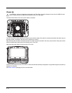
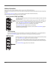
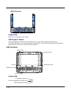
External Connectors
Power the Thor VM1 off before attaching a cable to any port (serial, USB, Audio/CAN, etc.).
The external I/O connectors for the Thor VM1 are located on the right side of the Quick Mount Smart Dock (when viewed from
the back).
The Power Supply Connector (page 3-7) is on the left side of the dock (when viewed from the back).
Antenna connectors are located on the top rear of the Thor VM1.
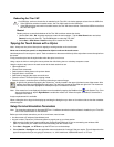
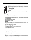
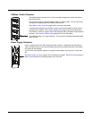
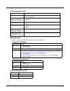
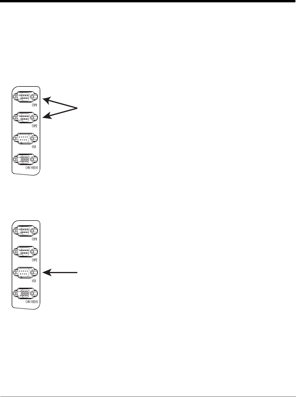
Serial Connector (COM1 and COM2)
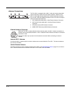
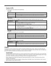
Screen Blanking
The screen blanking signal can be provided either by a Honeywell Screen Blanking Box or a user supplied switch or
relay. See Screen Blanking (page 4-44) for information on connecting screen blanking accessories.
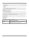
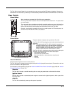
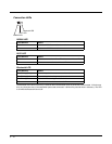
USB Connector
The COM1 and COM2 connectors are D-9 male connectors located on the back of the Quick
Mount Smart Dock.
Power the Thor VM1 off before attaching a cable to any port (serial, USB, Audio/CAN, etc.).
The serial connectors are industry-standard RS-232, PC/AT standard 9–pin “D” male con-
nector. See COM1 and COM2 Connector (page 8-4) for connector pinout detail.
Pin 9 is configured to provide +5V for an external bar code scanner.
See Connect Serial Device (page 4-48) for more information.
If a COM port is not being used for a scanner, it can be used for Screen Blanking (page 4-
44) when the vehicle is in motion.
The USB connector is a D-9 female connector located on the back of the Quick Mount Smart
Dock. See USB Connector (page 10-5) for connector pinout detail.
Power the Thor VM1 off before attaching a cable to any port (serial, USB, Audio/CAN, etc.).
The USB client port is not supported with Windows Embedded Standard 2009 operating sys-
tems.
See Connect USB Host (page 4-33) for more information.