


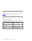
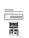
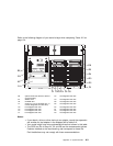
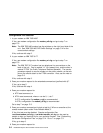
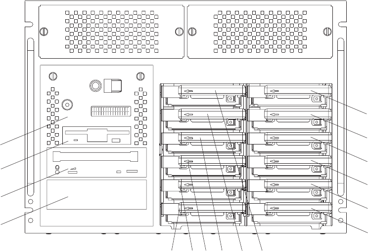
Refer to the following diagram of your server's bays when completing Table A-2 on
page A-4.
disc
c
D
C3
D3
C6
C2
A2
A1
B1
B2
D6
D2
C5
C1
D5
D4
D1
C4
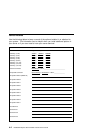
Notes:
If you attach a drive or other device to an adapter, record the expansion-
slot number for that adapter in the Adapter field of table A-2.
Your model might have more preinstalled drives than shown in this table.
The SCSI bus IDs in Bays A1, B1 and B2 are the recommended values.
Features installed at the manufacturing site correspond to these IDs.
Field installations may not comply with these recommendations.
B2 optional SCSI boot disk drive (behind
op panel display)
C2 hot-swappable disk drive
B1 diskette drive C3 hot-swappable disk drive
A2 CD-ROM drive D6 hot-swappable disk drive
A1 media bay (can be CD-ROM, tape, or
non-hot-swappable hard disk drive)
D5 hot-swappable disk drive
C6 hot-swappable disk drive D4 hot-swappable disk drive
C5 hot-swappable disk drive D1 hot-swappable disk drive
C4 hot-swappable disk drive D2 hot-swappable disk drive
C1 hot-swappable disk drive D3 hot-swappable disk drive
Appendix A. System Records A-3