


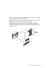
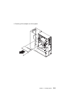
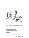
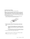
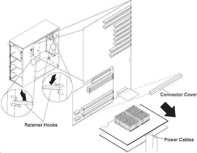
b. Open the retainer hooks on the unused CPU card slot.
c. Remove the connector cover from the unused CPU card slot.
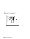
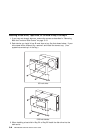
d. Place the new CPU card in the card guide rails.
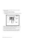
e. Make sure that the black tabs on the new card are captured by the retainer
hooks.
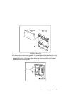
f. Align the card with the connectors.
g. Close the retainer hooks to set the card.
Attention: To prevent damage to the card and the card connectors, open
and close the retainer hooks at the same time.
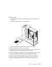
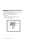
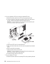
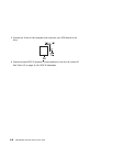
h. Connect the power cable to each of the CPU cards.
i. Ensure that the power cables come out vertically from the power supply and
that they are pushed back and out of the way so that the I/O planar cover
can be installed.
8. If you have other procedures to perform, refer to “Option List” on page 5-17.
9. If you do not have any other procedures to perform, replace the I/O planar cover
as described in “Replacing the I/O Planar Cover” on page 5-101; then return
here to determine your next step.
Chapter 5. Installing Options 5-39