Thermal Metrology
18 Intel® 631xESB/632xESB I/O Controller Hub Thermal Mechanical Design Guide
Note:
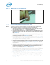
1. Three axes set consists of (1ea. U-31CF), (1ea. UX-6-6), (1ea. USM6) and (1ea. UPN-1). More information
available at: http://www.narishige.co.jp/you_ltd/english/products/set/you-set.htm#3.
5.1.2 Thermal Calibration and Controls
It is recommended that full and routine calibration of temperature measurement
equipment be performed before attempting to perform temperature case measurement
of the Intel 5000 Series chipset MCH. Intel recommends checking the meter probe set
against known standards. This should be done at 0ºC (using ice bath or other stable
temperature source) and at an elevated temperature, around 80ºC (using an
appropriate temperature source).
Wire gauge and length also should be considered as some less expensive measurement
systems are heavily impacted by impedance. There are numerous resources available
throughout the industry to assist with implementation of proper controls for thermal
measurements.
Note:
1. It is recommended to follow company standard procedures and wear safety items
like glasses for cutting the IHS and gloves for chemical handling.
2. Ask your Intel field sales representative if you need assistance to groove and/or
install a thermocouple according to the reference process.
5.1.3 IHS Groove
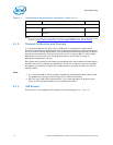
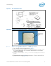
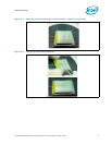
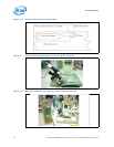
Cut a groove in the package IHS according to the drawing given in. Figure 5-1.
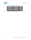
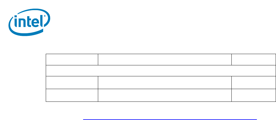
Calibration and Control
Ice Point* Cell Omega, stable 0°C temperature source for calibration and
offset
TRCIII
Hot Point* Cell Omega, temperature source to control and understand meter
slope gain
CL950-A-110
Table 5-1. Thermocouple Attach Support Equipment (Sheet 2 of 2)
Item Description Part Number


