


Introduction
8 Intel® 5000 Series Chipset Memory Controller Hub (MCH) Thermal Mechanical Design Guide
1.2 Definition of Terms
BGA Ball grid array. A package type, defined by a resin-fiber
substrate, onto which a die is mounted, bonded and
encapsulated in molding compound. The primary electrical
interface is an array of solder balls attached to the substrate
opposite the die and
molding compound.
BLT Bond line thickness. Final settled thickness of the thermal
interface material after installation of heatsink.
Intel
®
631xESB/632xESB I/O Controller Hub
The chipset component that integrates an Ultra ATA 100
controller, six Serial ATA host controller ports, one EHCI host
controller, and four UHCI host controllers supporting eight
external USB 2.0 ports, LPC interface controller, flash BIOS
interface controller, PCI interface controller, Azalia / AC’97
digital controller, integrated LAN controller, an ASF controller
and a ESI for communication with the MCH. The Intel 631xESB/
632xESB I/O Controller Hub component provides the data
buffering and interface arbitration required to ensure that
system interfaces operate efficiently and provide the bandwidth
necessary to enable the system to obtain peak performance.
MCH Memory controller hub. The chipset component that contains
the processor interface, the memory interface, the PCI Express*
interface and the ESI interface.
PXH Intel
®
6700PXH 64-bit PCI Hub. The chipset component that
performs PCI bridging functions between the PCI Express
interface and the PCI Bus. It contains two PCI bus interfaces
that can be independently configured to operate in PCI (33 or 66
MHz) or PCI-X* mode 1 (66, 100 or 133 MHz), for either 32 or
64 bit PCI devices.
PXH-V Intel
®
6702PXH 64-bit PCI Hub. The chipset component that
performs PCI bridging functions between the PCI Express
interface and the PCI Bus. It contains one PCI bus interface that
can be configured to operate in PCI (33 or 66MHz) or PCI-X
mode 1 (66, 100 or 133 MHz).
T
case_max
Maximum IHS temperature allowed. This temperature is
measured at the geometric center of the top of IHS.
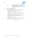
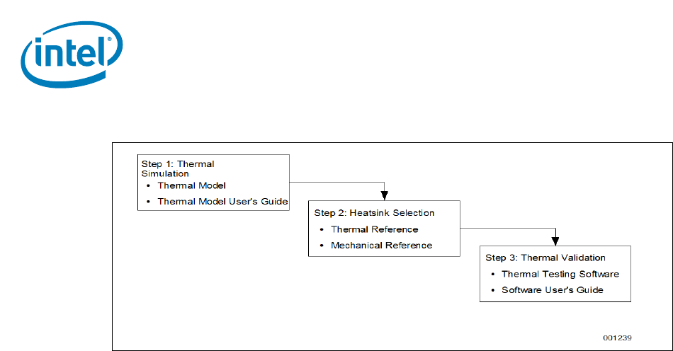
Figure 1-1. Thermal Design Process