


Intel® 5000 Series Chipset Memory Controller Hub (MCH) Thermal Mechanical Design Guide 3
Contents
1Introduction..............................................................................................................7
1.1 Design Flow........................................................................................................7
1.2 Definition of Terms ..............................................................................................8
1.3 Reference Documents ..........................................................................................9
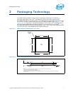
2 Packaging Technology ............................................................................................. 11
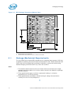
2.1 Package Mechanical Requirements....................................................................... 12
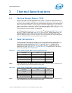
3 Thermal Specifications ............................................................................................ 13
3.1 Thermal Design Power (TDP) .............................................................................. 13
3.2 Case Temperature............................................................................................. 13
4 Thermal Simulation ................................................................................................. 15
5 Thermal Metrology .................................................................................................. 17
5.1 MCH Case Temperature Measurement .................................................................. 17
5.1.1 Supporting Test Equipment...................................................................... 17
5.1.2 Thermal Calibration and Controls.............................................................. 18
5.1.3 IHS Groove ........................................................................................... 18
5.1.4 Thermocouple Conditioning and Preparation............................................... 19
5.1.5 Thermocouple Attachment to the IHS........................................................ 20
5.1.6 Curing Process....................................................................................... 23
5.1.7 Thermocouple Wire Management.............................................................. 24
5.1.8 Power Simulation Software ...................................................................... 25
6 Reference Thermal Solution..................................................................................... 27
6.1 Operating Environment ...................................................................................... 27
6.2 Heatsink Performance........................................................................................ 27
6.3 Mechanical Design Envelope ............................................................................... 28
6.4 Board-Level Components Keepout Dimensions ...................................................... 28
6.5 Tall Torsional Clip Heatsink Thermal Solution Assembly .......................................... 29
6.5.1 Heatsink Orientation............................................................................... 30
6.5.2 Extruded Heatsink Profiles....................................................................... 31
6.5.3 Mechanical Interface Material................................................................... 31
6.5.4 Thermal Interface Material....................................................................... 31
6.5.5 Heatsink Clip ......................................................................................... 31
6.5.6 Clip Retention Anchors ............................................................................ 32
6.6 Reliability Guidelines.......................................................................................... 32
7 Reference Thermal Solution 2.................................................................................. 35
7.1 Operating Environment ...................................................................................... 35
7.2 Heatsink Performance........................................................................................ 35
7.3 Mechanical Design Envelope ............................................................................... 36
7.4 Board-Level Components Keepout Dimensions ...................................................... 36
7.5 Short Torsional Clip Heatsink Thermal Solution Assembly........................................ 37
7.5.1 Heatsink Orientation............................................................................... 38
7.5.2 Extruded Heatsink Profiles....................................................................... 39
7.5.3 Mechanical Interface Material................................................................... 39
7.5.4 Thermal Interface Material....................................................................... 39
7.5.5 Clip Retention Anchors ............................................................................ 39
7.6 Reliability Guidelines.......................................................................................... 39