


Intel® 631xESB/632xESB I/O Controller Hub Thermal Mechanical Design Guide 35
Reference Thermal Solution 2
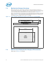
7 Reference Thermal Solution 2
Intel has developed two different reference thermal solutions to meet the cooling needs
of the Intel 5000 Series chipset MCH under operating environments and specifications
defined in this document. This chapter describes the overall requirements for the short
torsional clip heatsink reference thermal solution including critical-to-function
dimensions, operating environment, and validation criteria. Other chipset components
may or may not need attached thermal solutions, depending on your specific system
local-ambient operating conditions. For information on the PXH, refer to thermal
specification in the Intel
®
6700PXH 64-bit PCI Hub Thermal/Mechanical Design
Guidelines. For information on the Intel
®
631xESB/632xESB I/O Controller Hub, refer
to thermal specifications in the Intel
®
631xESB/632xESB I/O Controller Hub Thermal/
MechanicalDesign Guidelines.
7.1 Operating Environment
The reference thermal solution was designed assuming a maximum local-ambient
temperature of 55°C. The minimum recommended airflow velocity through the cross-
section of the heatsink fins is 350 linear feet per minute (lfm). The approaching airflow
temperature is assumed to be equal to the local-ambient temperature. The thermal
designer must carefully select the location to measure airflow to obtain an accurate
estimate. These local-ambient conditions are based on a 35°C external-ambient
temperature at sea level. (External-ambient refers to the environment external to the
system.)
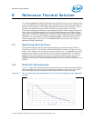
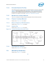
7.2 Heatsink Performance
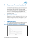
Figure 7-1 depicts the measured thermal performance of the reference thermal solution
versus approach air velocity. Since this data was measured at sea level, a correction
factor would be required to estimate thermal performance at other altitudes.
Figure 7-1. Short Torsional Clip Heatsink Measured Thermal Performance Versus
Approach Velocity