


Intel® 631xESB/632xESB I/O Controller Hub Thermal Mechanical Design Guide 23
Thermal Metrology
5.1.6 Curing Process
1. Let the thermocouple attach sit in the open air for at least half an hour. Using any
curing accelerator like Loctite 7452 Accelerator* for this step is not recommended.
Rapid contraction of the adhesive during curing may weaken bead attach on the
IHS.
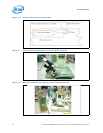
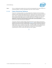
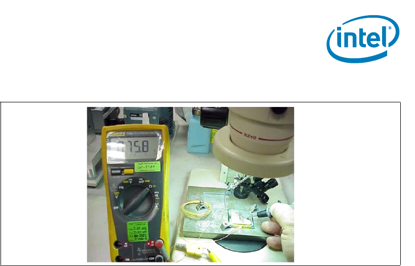
2. Reconfirm electrical connectivity with DMM before removing the micromanipulator
(Figure 5-8) (see Section 5.1.4, “Thermocouple Conditioning and Preparation” on
page 19 step 2).
3. Remove the 3D Arm needle by holding down the MCH unit and lifting
the arm.
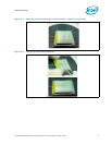
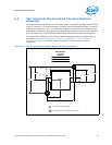
4. Remove the Kapton tape, straighten the wire in the groove so it is flat all the way to
the end of the groove (Figure 5-11).
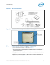
5. Using a blade, shave excess adhesive above the IHS surface (Figure 5-11).
Note: Take usual precautions when using open blades.
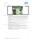
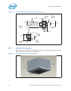
6. Install new Kapton tape to hold the thermocouple wire down and fill the rest of
groove with adhesive (See Figure 5-12). Make sure the wire and insulation is
entirely within the groove and below the IHS surface.
7. Curing time for the rest of the adhesive in the groove can be reduced using Loctite
7452 Accelerator.
8. Repeat step 5 to remove any access adhesive to ensure flat IHS for proper
mechanical contact to the heatsink surface.
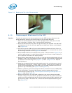
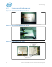
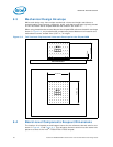
Figure 5-9. Applying the Adhesive on the Thermocouple Bead