


Reference Thermal Solution 2
36 Intel® 631xESB/632xESB I/O Controller Hub Thermal Mechanical Design Guide
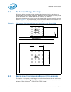
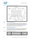
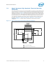
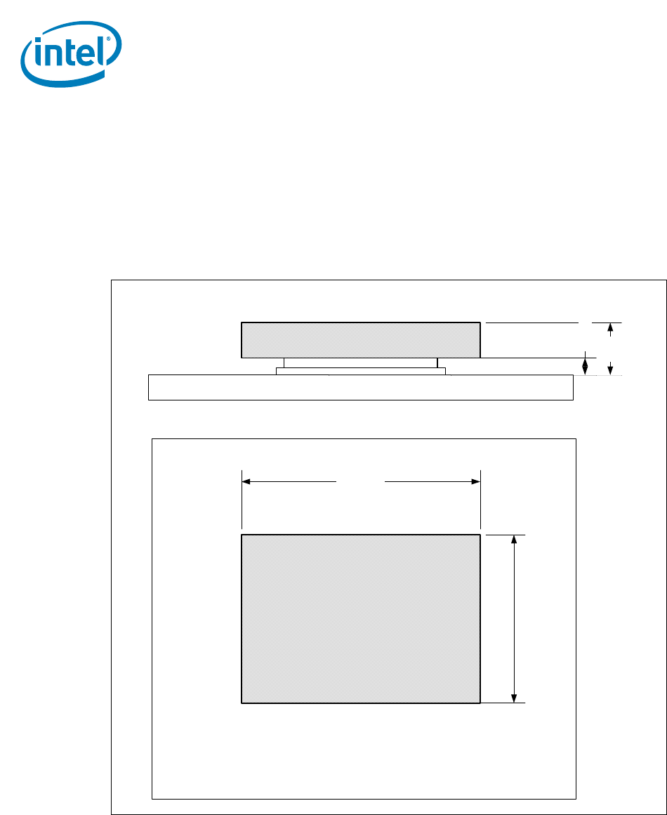
7.3 Mechanical Design Envelope
While each design may have unique mechanical volume and height restrictions or
implementation requirements, the height, width, and depth constraints typically placed
on the Intel 5000 Series chipset MCH thermal solution are shown in Figure 7-2.
When using heatsinks that extend beyond the chipset MCH reference heatsink envelope
shown in Section 7.2 any motherboard components placed between the heatsink and
motherboard cannot exceed 2 mm (0.07 in.) in height.
7.4 Board-Level Components Keepout Dimensions
Please refer to Section 6.5 for details.
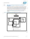
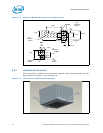
Figure 7-2. Short Torsional Clip Heatsink Volumetric Envelope for the Chipset MCH
TNB
Heatsink
42.30 mm.
60.00 mm.
MCH
Passive
Heatsink
IHS + TIM2
FCBGA + Solder Balls
12.65
Motherboard
MCH Passive Heatsink
4.30 mm.