


Intel® 631xESB/632xESB I/O Controller Hub Thermal Mechanical Design Guide 19
Thermal Metrology
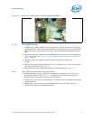
5.1.4 Thermocouple Conditioning and Preparation
1. Use a calibrated thermocouple as specified in Table 5-1.
2. Measure the thermocouple resistance by holding both wires on one probe and the
tip of thermocouple to the other probe of the DMM (compare to thermocouple
resistance specifications).
3. Straighten the wire for about 38 mm (1½ inch) from the bead to place it inside the
channel.
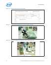
4. Bend the tip of the thermocouple to approximately a 45 degree angle by 0.8 mm
(0.030 inch) from the tip (Figure 5-3).
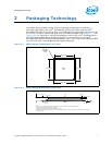
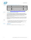
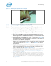
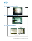
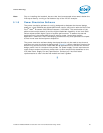
Figure 5-1. IHS Groove Dimensions
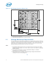
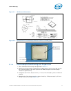
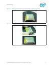
Figure 5-2. Orientation of Thermocouple Groove Relative to Package Pin