Developer’s Manual March, 2003 8-3
Intel
®
80200 Processor based on Intel
®
XScale
™
Microarchitecture
System Management
8.2 Processor Reset
The RESET# pin must be asserted when CLK and power are applied to the processor. CLK,
MCLK, and power must be present and stable before RESET# can be deasserted.
To ensure reset, RESET# must be asserted for at least 32 MCLK cycles once both clocks and the
power are stable. Reset pulses shorter than this have an undefined effect.
To simplify external reset circuitry, the Intel
®
80200 processor has a Schmitt trigger and an internal
pull-up resistor on RESET#. This allows a board to implement power-on reset simply by
connecting a 0.1 µF capacitor between RESET# and VSS
P
.
TRST#, the JTAG reset pin, must be asserted simultaneously with RESET#. It is permissible to
deassert it when RESET# is deasserted, or TRST# may remain asserted (tied to its active state).
Like RESET#, TRST# has a Schmitt trigger and internal pull-up, so it is permissible to tie these
together to a single external capacitor.
Hardware debug solutions may impose special requirements on RESET# and TRST#. Before
designing a board, consult the guidelines provided by the hardware debug solutions you may be
utilizing.
8.2.1 Reset Sequence
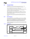
The output pin RESETOUT# is asserted when RESET# is asserted. The deassertion of RESET#
triggers an internal reset timer that keeps the Intel
®
80200 processor in a reset state until the PLL
has locked. CCLK is not running during this reset state and RESETOUT# remains asserted. When
the PLL is locked and stable, RESETOUT# is deasserted informing the system that the Intel
®
80200 processor has completed reset and CCLK is running. The time from the deasserting of
RESET# to the deassertion of RESETOUT# is approximately two thousand CLK cycles.
MCLK (input memory clock) must be stable, at a minimum, 10 CLK cycles before the deassertion
of RESET#. After RESETOUT# is deasserted, MCLK need only be present when the Intel
®
80200
processor external bus is active.
Figure 8-1. Reset Sequence
CCLK
CYCLE#
RESET#
0 ~2000
RESETOUT#
MCLK
CLK


