


Developer’s Manual March, 2003 7-21
Intel
®
80200 Processor based on Intel
®
XScale
™
Microarchitecture
Configuration
7.3.3 Registers 6-7: Clock and Power Management
These registers contain functions for managing the core clock and power.
Three low power modes are supported that are entered upon executing the functions listed in
Table 7-24. To enter any of these modes, write the appropriate data to CP14, register 7
(PWRMODE). Software may read this register, but since software only runs during ACTIVE
mode, it always reads zeroes from the M field.
Software can change the core clock frequency by writing to the CP 14 register 6, CCLKCFG. This
function waits for all the Intel
®
80200 processor initiated memory requests to complete and
informs the PLL to change the core clock frequency. This function completes when the PLL is
re-locked. Software can read CCLKCFG to determine current operating frequency.
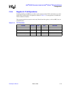
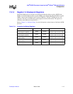
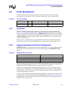
Table 7-23. PWRMODE Register
31 30 29 28 27 26 25 24 23 22 21 20 19 18 17 16 15 14 13 12 11 10 9 8 7 6 5 4 3 2 1 0
M
reset value: writeable bits set to 0
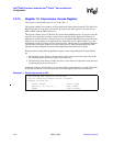
Bits Access Description
31:2 Read-unpredictable / Write-as-Zero Reserved
1:0 Read / Write
Mode (M)
0 = ACTIVE
2 = RESERVED
1 = IDLE
3 = SLEEP
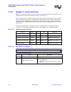
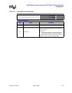
Table 7-24. Clock and Power Management
Function Data Instruction
Go to IDLE 1 MCR p14, 0, Rd, c7, c0, 0
Go to SLEEP 3 MCR p14, 0, Rd, c7, c0, 0
Read CCLKCFG ignored MRC p14, 0, Rd, c6, c0, 0
Write CCLKCFG CCLKCFG value MCR p14, 0, Rd, c6, c0, 0
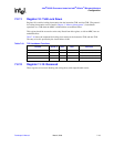
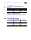
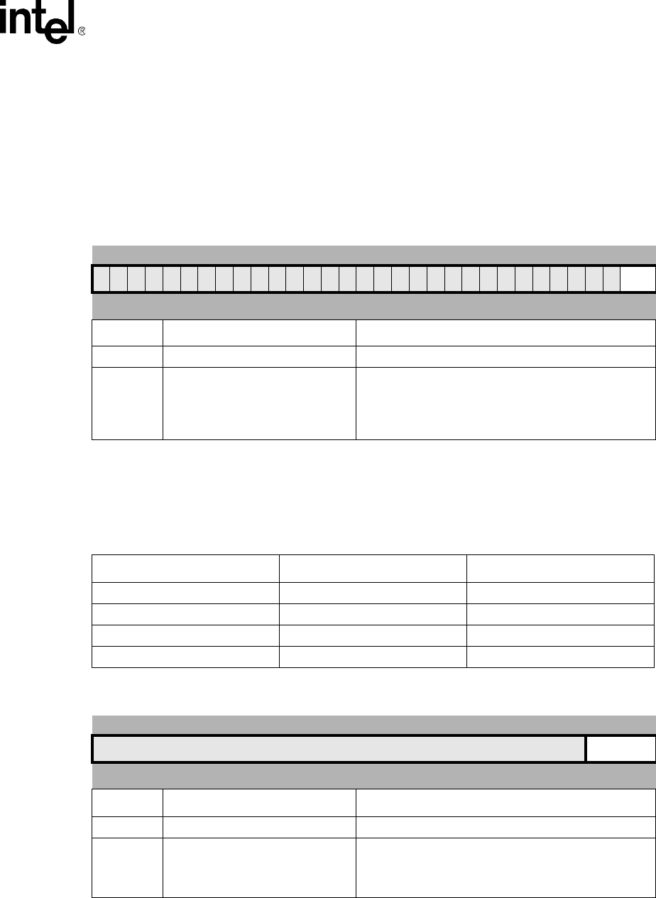
Table 7-25. CCLKCFG Register
31 30 29 28 27 26 25 24 23 22 21 20 19 18 17 16 15 14 13 12 11 10 9 8 7 6 5 4 3 2 1 0
CCLKCFG
reset value: unpredictable
Bits Access Description
31:4 Read-unpredictable / Write-as-Zero Reserved
3:0 Read / Write
Core Clock Configuration (CCLKCFG)
This field is used to configure the core clock frequency.
The value in this field is multiplied by REFCLK to obtain
core clock. See Table 8-2.