


Developer’s Manual March, 2003 C-3
Intel
®
80200 Processor based on Intel
®
XScale
™
Microarchitecture
Test Features
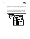
C.2.2 TAP Pins
The Intel
®
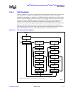
80200 processor TAP is composed of four input connections (TMS, TCK, TRST# and
TDI) and one output connection (TDO). These pins are described in Table C-1. The TAP pins
provide access to the instruction register and the test data registers.
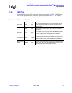
Table C-1. TAP Controller Pin Definitions
Pin Name Mnemonic Type Definition
Test Clock TCK Input
Clock input for the TAP controller, the instruction register, and the
test data registers. The JTAG unit retains its state when TCK is
stopped at “0” or “1”.
Test Mode
Select
TMS Input
Controls the operation of the TAP controller. The TMS input is
pulled high when not being driven. TMS is sampled on the rising
edge of TCK.
Test Data In TDI Input
Serial date input to the instruction and test data registers. Data at
TDI is sampled on the rising edge of TCK. Like TMS, TDI is pulled
high when not being driven. Data shifted from TDI through a
register to TDO appears non-inverted at TDO.
Test Data Out TDO Output
Used for serial data output. Data at TDO is driven at the falling edge
of TCK and provides an inactive (high-Z) state when scanning is not
in progress. The non-shift inactive state is provided to support
parallel connection of TDO outputs at the board or module level.
Asynchronous
Reset
TRST# Input
Provides asynchronous initialization of the test logic. TRST# is
pulled low when not being driven. Assertion of this pin puts the TAP
controller in the Test_Logic_Reset (initial) state
. An external source
drives this signal high for TAP controller operation.