


C-4 March, 2003 Developer’s Manual
Intel
®
80200 Processor based on Intel
®
XScale
™
Microarchitecture
Test Features
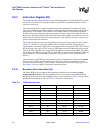
C.2.3 Instruction Register (IR)
The instruction register holds instruction codes shifted through the Test Data Input (TDI) pin. The
instruction codes are used to select the specific test operation to be performed and the test data
register to be accessed.
The instruction register is a parallel-loadable, master/slave-configured 5-bit wide, serial-shift
register with latched outputs. Data is loaded into the IR serially through the TDI pin clocked by the
rising edge of TCK when the TAP controller is in the Shift_IR state. The shifted-in instruction
becomes active upon latching from the master-stage to the slave-stage in the Update_IR state. At
that time the IR outputs along with the TAP finite state machine outputs are decoded to select and
control the test data register selected by that instruction. Upon latching, all actions caused by any
previous instructions must terminate.
The instruction determines the test to be performed, the test data register to be accessed, or both
(Table C-2). The IR is five bits wide. When the IR is selected in the Shift_IR state, the most
significant bit is connected to TDI, and the least significant bit is connected to TDO. TDI is shifted
into IR on each rising edge of TCK, as long as TMS remains asserted. When the processor enters
Capture_IR TAP controller state, fixed parallel data (0001
2
) is captured. During Shift_IR, when a
new instruction is shifted in through TDI, the value 0001
2
is always shifted out through TDO least
significant bit first. This helps identify instructions in a long chain of serial data from several
devices.
Upon activation of the TRST# pin, the latched instruction asynchronously changes to the idcode
instruction. If the TAP controller moved into the Test_Logic_Reset state other than by reset
activation, the opcode changes as TDI is shifted, and becomes active on the falling edge of TCK.
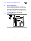
See Figure C-4 for an example of loading the instruction register.
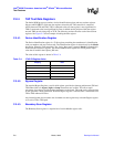
C.2.3.1. Boundary-Scan Instruction Set
The Intel
®
80200 processor supports three mandatory boundary scan instructions (bypass,
sample/preload and extest). The Intel
®
80200 processor also contains seven additional public
instructions along with seven Intel
®
80200 processor private instructions. Table C-2 lists the Intel
®
80200 processor instruction codes and Table C-3 describes each instruction.
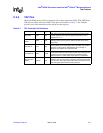
Table C-2. JTAG Instruction Set
Instruction Code Instruction Name Instruction Code Instruction Name
00000
2
extest
01011
2
private
00001
2
sample
01100
2
private
00010
2
dbgrx 01101
2
private
00011
2
private 01110
2
not used
00100
2
clamp
01111
2
not used
00101
2
private 10000
2
dbgtx
00110
2
not used 10001
2
not used
00111
2
ldic 10010
2
not used
01000
2
highz
10011
2
through 11101
2
not used
01001
2
dcsr 11110
2
idcode
01010
2
private 11111
2
bypass