


C-2 March, 2003 Developer’s Manual
Intel
®
80200 Processor based on Intel
®
XScale
™
Microarchitecture
Test Features
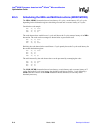
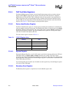
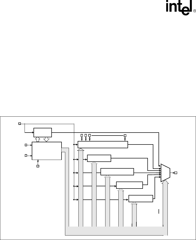
C.2.1 Boundary Scan Architecture
Boundary scan test logic consists of a Boundary-Scan register and support logic. These are
accessed through a Test Access Port (TAP). The TAP provides a simple serial interface that allows
all processor signal pins to be driven and/or sampled, thereby providing the direct control and
monitoring of processor pins at the system level.
This mode of operation is valuable for design debugging and fault diagnosis since it permits
examination of connections not normally accessible to the test system. The following subsections
describe the boundary scan test logic elements: TAP pins, instruction register, test data registers,
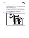
and TAP controller. Figure C-1 illustrates how these pieces fit together to form the JTAG unit.
To ensure that the processor does not enter an invalid state during boundary scan, it must have
received a valid reset (on RESET#) including a valid clock input (on clk).
Figure C-1. Test Access Port Block Diagram
ID Reg / 32
ldic / 33
debug / 36
TDO
TRST#
TDI
TMS
TCK
Tap
Controller
Bypass Reg / 1
Control And Clock Signals
Boundary Scan Chain
I R / 5