


C-12 March, 2003 Developer’s Manual
Intel
®
80200 Processor based on Intel
®
XScale
™
Microarchitecture
Test Features
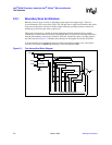
C.2.5.17. Boundary-Scan Example
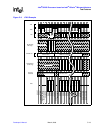
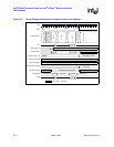
In the example that follows, two command actions are described. The example starts in the reset
state, a new instruction is loaded and executed. See Figure C-3 for a JTAG example. The steps are:
1. Load the sample/preload instruction into the Instruction Register:
a. Select the Instruction register scan.
b. Use the Shift-IR state four times to read the least through most significant instruction bits
into the instruction register (we do not care that the old instruction is being shifted out of
the TDO pin).
c. Enter the Update-IR state to make the instruction take effect.
d. Exit the Instruction register.
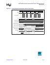
2. Capture and shift the data onto the TDO pin:
a. Select the Data register scan state.
b. Capture the pin information into the n-stage Boundary-Scan register.
c. Enter and stay in the shift-DR state for n cycles. These TDO values are compared against
expected data to determine if component operation and connection are correct. Record the
TDO value after each cycle. New serial data enters the boundary-scan register through the
TDI pin, while old data is scanned out.
d. Pass through the Exit1-DR and Update-DR to continue.
This example does not make use of the pause states. Those states would be more useful where we
do not control the clock directly. The pause states let the clock tick without affecting the shift
registers.
The old instruction was abcd in the example. It is known that the original value is the ID code since
the example starts from the reset state. Other times it represents the previous opcode. The new
instruction opcode is 0001
2
(sample/preload). All pins are captured into the serial Boundary-Scan
register and the values are output to the TDO pin.
The clock signal drawn at the top of the diagram is drawn as a stable symmetrical clock. This is not
in practice the most common case. Instead the clocking is usually done by a program writing to a
port bit. The TMS and TDI signals are written by software and then the software makes the clock
go high. The software typically often lowers the clock input quickly. The program can then read
the TDO pin.