


16 Intel ISP1100 Internet Server Product Guide
Keyboard and Mouse Interface
The PS/2 keyboard and mouse connectors are located on the server back panel. The +5 V lines to
these connectors are protected with a PolySwitch
†
circuit that, like a self-healing fuse, reestablishes
the connection after an overcurrent condition is removed.
The keyboard controller contains the AMI keyboard and mouse controller code, provides the
keyboard and mouse control functions, and supports password protection for power on/reset. A
power on/reset password can be specified in the BIOS Setup.
The keyboard controller also supports the hot-key sequence <Ctrl><Alt><Del> for a software
reset. This key sequence resets the computer software by jumping to the beginning of the BIOS
code and running the Power-On Self-Test (POST).
NOTE
The mouse and keyboard can be plugged into either of the PS/2 connectors.
Turn off AC power to the computer before a keyboard or mouse is connected
or disconnected.
Hardware Monitor
A Heceta 2 system monitor controller is provided on the server board to monitor temperature,
voltage, fan speed and a temperature sensor located on the front panel. Temperature is monitored
through a sensor internal to the Heceta 2 that indicates the ambient temperature of the area of the
board in which the Heceta 2 IC is located. The Heceta 2 monitors +5V, +3.3V, +12V, –12V,
+1.5V, and the processor core voltage. The Heceta 2 may be used to monitor the speed of a fan that
has a tachometer output connected to any of the five auxiliary fan connectors. The five system fan
tachometer outputs are multiplexed to the Heceta 2 device to allow individual monitoring. The
software through the PIIX4 chip controls the multiplexing of the fan tachometer outputs to the
Heceta 2 chip. The multiplexer control bits (FAN_MUXCTL0 and FAN_MUXCTL1) are
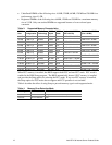
connected to the PIIX4 are connected to the outputs GPO0 and GPO13, respectively. Table 5
shows the fan tachometer mapping.
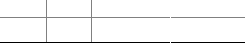
Table 5. Fan Tachometer MUX Control Mapping
Fan_MUXCTL0 Fan_MUXCTL1 Heceta FAN1_TACH Input Heceta FAN2_TACH Input
0 0 Fan 1 (J35) Fan 4 (J38)
0 1 Fan 2 (J34) Fan 5 (J37)
1 0 Fan 3 (J33) NONE
1 1 NONE NONE
The Heceta 2 is set up and interfaced through the PIIX4 SMBUS interface. Out of band or absolute
thresholds may be set for many of the monitored functions using the SMBUS interface. Threshold
faults are available by polling the Heceta 2 via the SMBUS interface. The Heceta 2 updates its
information approximately every 1 second.