KS152JB Universal Communications Controller
Technical Specifications
Kawasaki LSI USA, Inc. Page 105 of 120 Ver. 0.9 KS152JB2
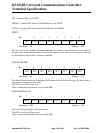
IPN1 (0F8H)
Allows the user software two levels of prioritization to be assigned to each of the interrupts in
IEN1. A 1 assigns the corresponding interrupt in IEN1 a higher interrupt than an interrupt with a
corresponding 0.
IPN1.0 (PGSRV) - Assigns the priority of GSC receive valid interrupt.
IPN1.1 (PGSRE) - Assigns the priority of GSC error receive interrupt.
IPN1.2 (PDMA0) - Assigns the priority of DMA done interrupt for Channel 0.
IPN1.3 (PGSTV) - Assigns the priority of GSC transmit valid interrupt.
IPN1.4 (PDMA1) - Assigns the priority of DMA done interrupt for Channel 1.
IPN1.5 (PGSTE) - Assigns the priority of GSC transmit error interrupt.
ISA - Increment Source Address, see DCON0.
LNI - Line Idle, see TSTAT.
LSC - Local Serial Channel - The asynchronous serial port found on all MCS-51 devices. Uses
start/stop bits and can transfer only 1 bit at a time.
M0 - One of two GSC mode bits, see TMOD.
M1 - One of the two GSC mode bits, see TMOD.
MYSLOT - (0F5H)
Determines which type of Jam is used, which backoff algorithm is used and DCR slot address for
the GSC.
MYSLOT.0,1,2,3,4,5 (SA0,1,2,3,4,5) - These bits determine which slot address is assigned to the
C152 when deterministic backoff during CSMA/CD operations on the GSC. Maximum slots avail-
able is 63. An address of 00H prevents that station from participating in the backoff process.
MYSLOT.6 (DCR) - Determines which collision resolution algorithm is used. If set to 1, then the
deterministic backoff is used. If cleared, then a random slot assignment is used.
01234567
PDMA1 PGSTV PDMA0 PGSRE PGSRVPGSTE
01234567
SA4 SA3 SA2 SA1 SA0SA5DCRDCJ


