KS152JB Universal Communications Controller
Technical Specifications
Kawasaki LSI USA, Inc. Page 13 of 120 Ver. 0.9 KS152JB2
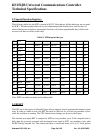
The “Timer” or “Counter” function is selected by the “C/T” bit in the TMOD Special Function
Register. Each Timer/Counter has one selection bit for its own; bit 2 of TMOD selects the func-
tion for Timer/Counter 0 and bit 6 of TMOD selects the function for Timer/Counter 1. In addition
each Timer/Counter can be set to operate in any one of four possible modes. The mode selection
is done by bits M0 and M1 in the TMOD SFR. Modes 0, 1 and 2 are identical for both the Timer/
Counters, but Mode 3 is different. The four modes of operation are described below.
MODE 0
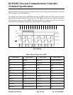
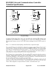
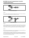
In Mode 0, the timer/counters act as a 8 bit counter with a 5 bit, divide by 32 prescaler. In this
mode we have a 13 bit timer/counter. The 13 bit counter consists of 8 bits of THx and 5 lower bits
of TLx. The upper 3 bits of TLx are ignored.
The negative edge of the clock increments the count in the TLx register. When the fifth bit in TLx
moves from 1 to 0, then the count in the THx register is incremented. When the count in THx
moves from FFh to 00h, then the overflow flag TFx in TCON SFR is set.
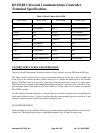
The counted input is enabled only if TRx is set and either GATE = 0 or
INTx = 1.
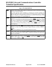
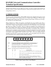
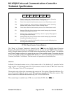
TF1 TR1 TF0 TR0 IE1 IT1 IE0 IT0
76543210
TF1 Timer 1 overflow flag. Set by hardware on Timer/Counter overflow. Cleared by
hardware when processor vectors to timer 1 interrupt routine.
Timer 1 Run control bit. Set/Cleared by software to turn Timer/Counter on/off.TR1
TF0
TR0
Timer 0 overflow flag. Set by hardware on Timer/Counter overflow. Cleared by
hardware when processor vectors to timer 0 interrupt routine.
Timer 0 Run control bit. Set/Cleared by software to turn Timer/Counter on/off.
Interrupt 1 Edge flag. Set by hardware when external interrupt edge is detected.
Cleared when interrupt is processed.
Interrupt 1 Type control bit. Set/ Cleared by software to specify falling edge/low
level triggered external interrupt.
Interrupt 0 Edge flag. Set by hardware when external interrupt edge id detected.
Cleared when interrupt is processed.
Interrupt 0 Type control bit. Set/Cleared by software to specify falling edge /low
level triggered external interrupt.
IE1
IT1
IE0
IT0
TCON: Timer/Counter Control Register.


