KS152JB Universal Communications Controller
Technical Specifications
Kawasaki LSI USA, Inc. Page 79 of 120 Ver. 0.9 KS152JB2
during the DMA, so interrupt flags may get set, but since program execution is suspended, the
interrupts will not be serviced while the DMA is in progress.
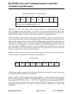
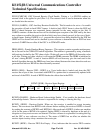
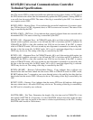
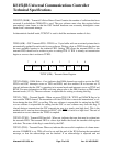
4.1.3 SERIAL PORT DEMAND MODE
In this mode the DMA can be used to service the Local Serial Channel (LSC) or the Global Serial
Channel (GSC).
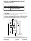
In Serial Port Demand Mode the DMA is initiated by any of the following conditions, if the GO
bit is set:
Source Address = SBUF .AND. RI = 1
Destination Address = SBUF .AND. TI = 1
Source Address = RFIFO .AND. RFNE = 1
Destination Address = TFIFO .AND. TFNF = 1
Each time one of the above conditions is met, one DMA Cycle is executed; that is, one data byte is
transferred from the source address to the destination address. On-chip hardware then clears the
flag (RI, TI, RFNE, or TFNF) that initiated the DMA, and decrements BCRn. Note that since the
flag that initiated the DMA is cleared, it will not generate an interrupt unless DMA servicing may
be held off when alternate cycle is being used or by the status of the HOLD/HLDA logic. In these
situations the interrupt for the LSC may occur before the DMA can clear the RI or TI flag. This is
because the LSC is serviced according to the status of RI and TI, whether or not the DMA chan-
nels are being used for the transferring of data. The GSC does not use RFNE or TFNF flags when
using the DMA channels so these do not need to be disabled. When using the DMA channels to
service the LSC it is recommended that the interrupts (RI and TI) be disabled. If the decremented
BCRn is 0000H, on-chip hardware then clears the GO bit and sets the DONE bit. The DONE bit
flags an interrupt.
4.1.4 EXTERNAL DEMAND MODE
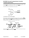
In External Demand Mode the DMA is initiated by one of the External Interrupt pins, provided
the GO bit is set.
INT0 initiates a Channel 0 DMA, and INT1 initiates a Channel 1 DMA.
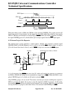
If the external interrupt is configured to be transition activated, then each 1-to-0 transition at the
interrupt pin sets the corresponding external interrupt flag, and generates one DMA Cycle. Then,
BCRn is decremented. No more DMA Cycles take place until another 1-to-0 transition is seen at
the external interrupt pin. IF THE DECREMENTED bcrN = 0000H, on-chip hardware clears the
GO bit and sets the DONE bit. If the external interrupt is enabled, it will be serviced.
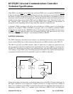
If the external interrupt is configured to be level-activated, then DMA Cycles commence when the
interrupt pin is pulled low, and continue for as long as the pin is held low and BCRn is not 0000H.
If BCRn reaches 0 while the interrupt pin is still low, the GO bit is cleared, the DONE bit is set,
and the DMA ceases. If the external interrupt is enabled, it will be serviced.
If the interrupt pin is pulled up before BCRn reaches 0000H, then the DMA ceases, but the GO bit


