


KS152JB Universal Communications Controller
Technical Specifications
Kawasaki LSI USA, Inc. Page 28 of 120 Ver. 0.9 KS152JB2
Baud Rates
In Mode 0 the baud rate is fixed at 1/12 of the oscillator frequency.
In Mode 2 the baud rate depends on the value of bit SMOD in PCON SFR. If SMOD is 0 then the
baud rate is 1/64 of the oscillator frequency. If the bit is set to 1, then the baud rate is 1/32 of the
oscillator frequency.
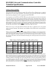
Mode 2 Baud Rate = 2
( SMOD - 6 )
X Oscillator Frequency
The baud rates in Mode 1 and 3 are determined by the overflow rates of Timer 1.
Using Timer 1 to generate baud rates.
When Timer 1 is used as a baud rate generator, the baud rates in Modes 1 and 3 are determined by
the Timer 1 overflow rate and the value of SMOD.
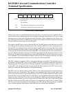
Modes 1 and 3 baud rate = 2
( SMOD - 5 )
X Timer 1 overflow rate
The Timer 1 interrupt should be disabled in this mode. The timer itself can be configured as either
“timer” or “counter”, in any of its 3 operating modes. Commonly, Timer 1 is configured as a timer
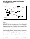
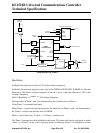
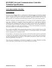
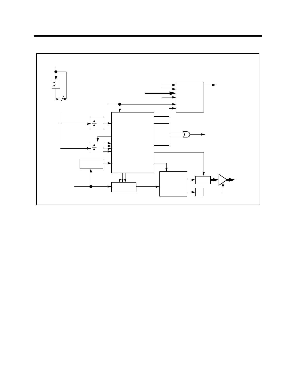
SOUT
STOP
D8
PARIN
START
LOAD
CLOCK
TX START
TX CLOCK
Transmit Shift Register
16
SIN
D8
PAROUT
CLOCK
BIT
DETECTOR
RX CLOCK
RX SHIFT
1-TO-0
DETECTOR
16
RX
SBUF
RB8
LOAD
SBUF
START
Read
SBUF
TX SHIFT
TI
RI
SERIAL
CONTROLLER
Write to
SBUF
Internal
Data Bus
0
TB8
1
Internal
Data Bus
RxD
TxD
Serial Interrupt
Receive Shift Register
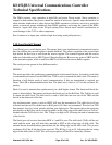
Local Serial Port Mode 3
2
SMOD
01
Timer 1
Overflow