KS152JB Universal Communications Controller
Technical Specifications
Kawasaki LSI USA, Inc. Page 95 of 120 Ver. 0.9 KS152JB2
= 0 Disable
EGSRE = 1 Enable GSC Receive Error Interrupt
= 0 Disable
EGSRV = 1 Enable GSC Receive Valid Interrupt
= 0 Disable
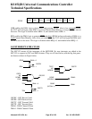
The two Interrupt Priority registers in the 8XC152 are as follows:
Address of IP in SFR space = 0B8H (bit-addressable)
Address of IPN1 in SFR space = 0F8H (bit -addressable)
The bits in IP are unchanged from the standard 8051 IP register. The bits in IPN1 are as follows:
PGSTE = 1 GSC Transmit Error Interrupt Priority to high
= 0 Priority to Low
PDMA1 = 1 DMA Channel 1 Done Interrupt Priority to high
= 0 Priority to Low
PGSTV = 1 GSC Transmit Valid Interrupt Priority to high
= 0 Priority to Low
PDMA0 = 1 DMA Channel 0 Done Interrupt Priority to high
= 0 Priority to Low
PGSRE = 1 GSC Receive Error Interrupt Priority to high
= 0 Priority to Low
PGSRV = 1 GSC Receive Valid Interrupt Priority to high
= 0 Priority to Low
Note that these registers all have unimplemented bits ("-"). If these bits are read, they will return
unpredictable values. If they are written to, the value written goes nowhere.
01234567
PS PT1 PX1 PT0 PX0
IP:
01234567
PDMA1 PGSTV PDMA0 PGSRE PGSRVPGSTE
IPN1:


