


KS152JB Universal Communications Controller
Technical Specifications
Kawasaki LSI USA, Inc. Page 118 of 120 Ver. 0.9 KS152JB2
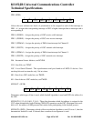
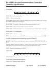
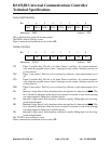
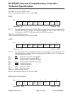
CY Carry flag: Set for an arithmetic operation which results in a carry being generated
from the ALU. It is also used as the accumulator for the bit operations.
AC Auxiliary carry: Set when the previous operation resulted in a carry (during addition0
or a borrow (during subtraction) from the high order nibble.
F0 User flag 0: General purpose flag that can be set or cleared by the user by software.
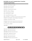
RS.1-0 Register bank select bits:
RS1 RS0 Register bank Address
0 0 0 00-07h
0 1 1 08-0Fh
1 0 2 10-17h
1 1 3 18-1Fh
OV Overflow flag: Set when a carry was generated from the seventh bit but not from the
8th bit as a result of the previous operation or vice-versa.
F1 User Flag 1: General purpose flag that can be set or cleared by the user by software
P Parity flag: Set/cleared by hardware to indicate odd/even number of 1’s in the accumu-
lator.
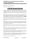
The PSW sfr is set to 00h by a reset.
There is unrestricted read/write access to this SFR.
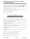
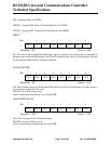
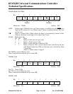
ACCUMULATOR
ACC.7-0 The A or ACC register is the accumulator
The ACC is reset to 00h on any reset
This sfr has unrestricted read/write access.
ACC.6
6
ACC.5
5
ACC.3
3
ACC.7
7
ACC.2
2
ACC.1
1
ACC.0
0
ACC.4
4
Bit:
Mnemonic: ACC Address: E0h