


KS152JB Universal Communications Controller
Technical Specifications
Kawasaki LSI USA, Inc. Page 113 of 120 Ver. 0.9 KS152JB2
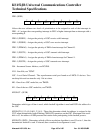
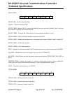
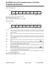
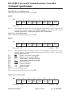
DATA POINTER HIGH
This is the high byte of the 16-bit data pointer.
The DPH is reset to 00h by a reset.
There is unrestricted read/write access to this SFR.
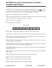
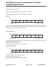
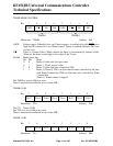
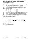
TIMER CONTROL
TF1 Timer 1 overflow flag: This bit is set when Timer 1 overflows. It is cleared automati-
cally when the program does a timer 1 interrupt service routine. Software can also set
or clear this bit.
TR1 Timer 1 run control: This bit is set or cleared by software to turn timer/counter on or
off.
TF0 Timer 0 overflow flag: This bit is set when Timer 0 overflows. It is cleared automati-
cally when the program does a timer 0 interrupt service routine. Software can also set
or clear this bit.
TR0 Timer 0 run control: This bit is set or cleared by software to turn timer/counter on or
off.
IE1 Interrupt 1 edge detect: Set by hardware when an edge/level is detected on
INT1. This
bit is cleared by hardware when the service routine is vectored to only if the interrupt
was edge triggered. Otherwise it follows the pin.
IT1 Interrupt 1 type control: Set/cleared by software to specify falling edge/ low level trig-
gered external inputs.
IE0 Interrupt 0 edge detect: Set by hardware when an edge/level is detected on
INT0. This
bit is cleared by hardware when the service routine is vectored to only if the interrupt
was edge triggered. Otherwise it follows the pin.
IT0 Interrupt 0 type control: Set/cleared by software to specify falling edge/ low level trig-
gered external inputs.
The TCON is reset to 00h by a reset.
There is unrestricted read/write access to this SFR.
DPH.6
6
DPH.5
5
DPH.3
3
DPH.7
7
DPH.2
2
DPH.1
1
DPH.0
0
DPH.4
4
Bit:
Mnemonic: DPH Address: 83h
TR1
6
TF0
5
IE1
3
TF1
7
IT1
2
IE0
1
IT0
0
TR0
4
Bit:
Mnemonic: TCON Address: 88h