


KS152JB Universal Communications Controller
Technical Specifications
Kawasaki LSI USA, Inc. Page 94 of 120 Ver. 0.9 KS152JB2
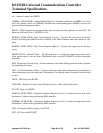
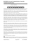
Note that the locations of the basic 8051 interrupts are the same as in the rest of the MCS-51 Fam-
ily. And relative to each other they retain the same positions in the polling sequence.
The locations of the new interrupts all follow the locations the basic 8051 interrupts in the Pro-
gram Memory, but they are interleaved with them in the polling sequence.
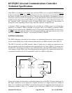
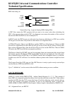
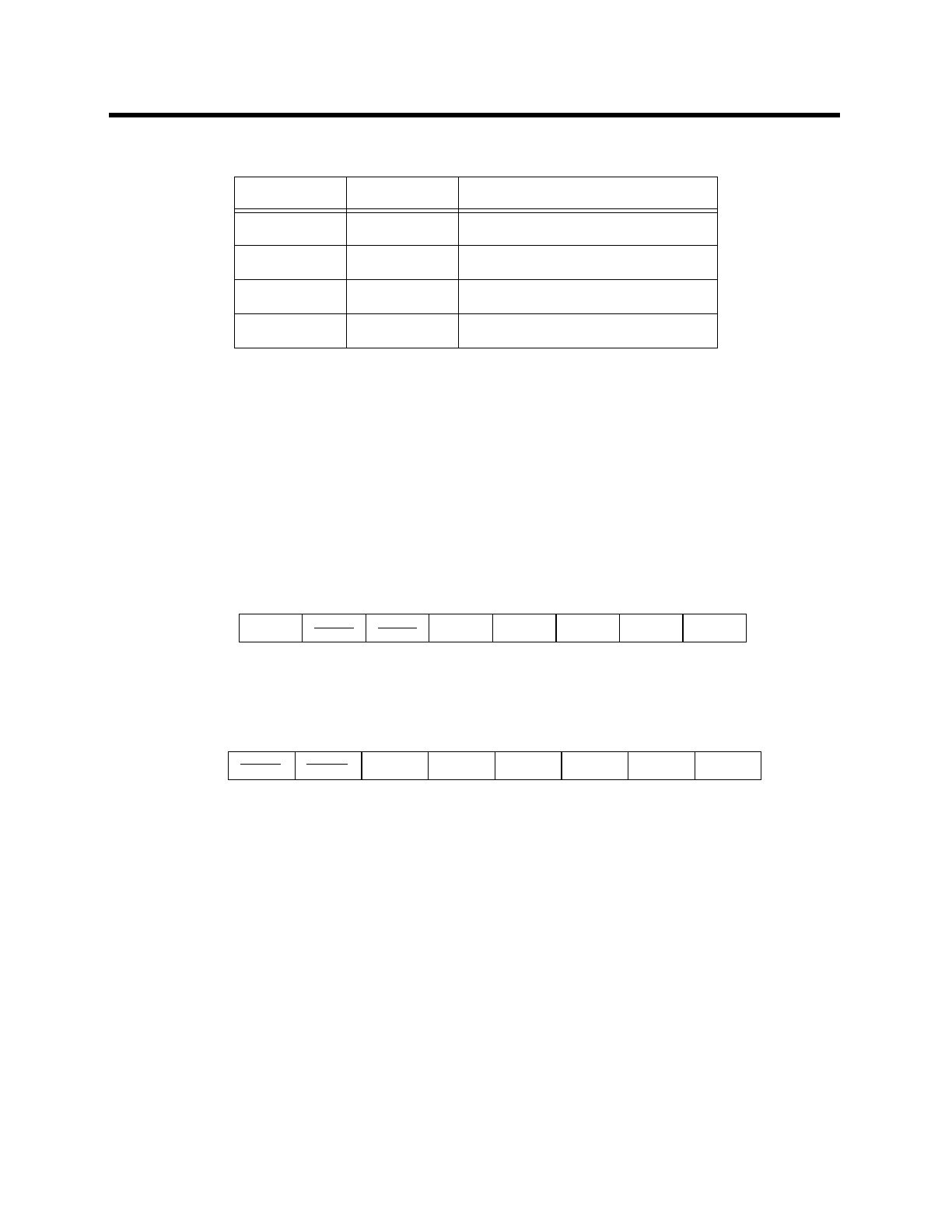
To support the new interrupts a second Interrupt Enable register and A second Interrupt Priority
register are implemented in the bit-addressable register space. The two Interrupt Enable registers
in the 8XC152 are as follows:
Address of IE in SFR space = 0A8H (bit-addressable)
Address of IE1 in SFR space = 0C8H (bit-addressable)
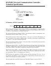
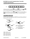
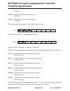
The bits in the IE are unchanged from the standard 8051 IE register. The bits in IEN1 are as fol-
lows:
EGSTE = 1 Enable GSC Transmit Error Interrupt
= 0 Disable
EDMA1 = 1 Enable DMA Channel 1 Done Interrupt
= 0 Disable
EGSTV = 1 Enable GSC Transmit Valid Interrupt
= 0 Disable
EDMA0 = 1 Enable DMA Channel 0 Done Interrupt
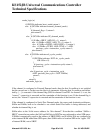
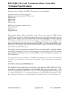
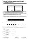
DMA1 0053H DMA Channel 1 Done
TF1 001BH Timer 1 Overflow
GSCTE 004BH GSC Transmit Error
TI+RI 0023H UART Transmit/Receive
Table 14:
Interrupt Location Name
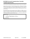
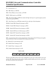
01234567
EA
ES ET1 EX1 ET0 EX0
IE:
01234567
EDMA1 EGSTV EDMA0 EGSRE EGSRVEGSTE
IEN1: