


KS152JB Universal Communications Controller
Technical Specifications
Kawasaki LSI USA, Inc. Page 114 of 120 Ver. 0.9 KS152JB2
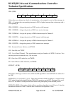
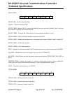
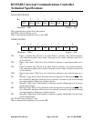
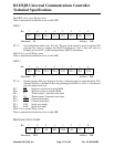
TIMER MODE CONTROL
GATE Gating control: When this bit is set, Timer/counter x is enabled only while
INTx pin is
high and TRx control bit is set. When cleared, Timerx is enabled whenever TRx con-
trol bit is set.
C/
T Timer or Counter Select: When cleared, the timer is incremented by internal clocks.
When set, the timer counts high-to-low edges of the Tx pin.
M1 M0 Mode Select bits:
M1 M0 Mode
0 0 Mode 0: 8-bits with 5-bit pre-scaler.
0 1 Mode 1: 18-bits, no pre-scaler.
1 0 Mode 2: 8-bits with auto-reload from THx
1 1 Mode 3: (Timer 0) TL0 is an 8-bit timer/counter controlled by the stan-
dard Timer 0 control bits. TH0 is a 8-bit timer only controlled by Timer
1 control bits.
(Timer 1) Timer/counter is stopped.
The TMOD is reset to 00h by a reset.
There is unrestricted read/write access to this SFR.
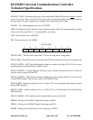
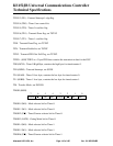
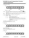
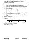
TIMER 0 LSB
TL0.7-0 Timer 0 LSB
The TL0 sfr is set to 00h on any reset.
There is unrestricted read/write access to this SFR.
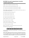
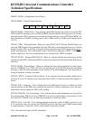
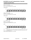
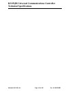
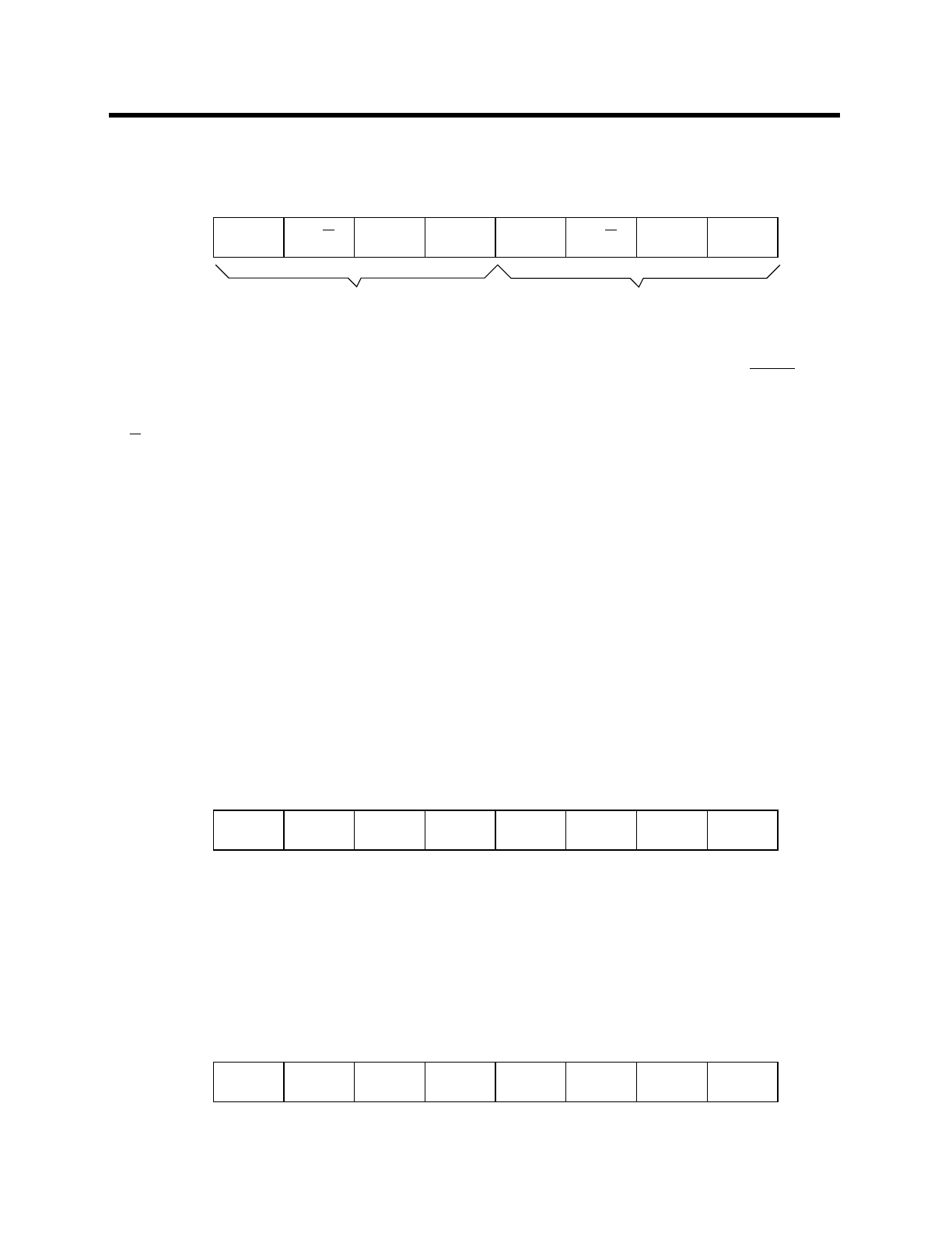
TIMER 1 LSB
C/T
6
M1
5
GATE
3
GATE
7
C/T
2
M1
1
M0
0
M0
4
Bit:
Mnemonic: TMOD Address: 89h
TIMER 1
TIMER 0
TL0.6
6
TL0.5
5
TL0.3
3
TL0.7
7
TL0.2
2
TL0.1
1
TL0.0
0
TL0.4
4
Bit:
Mnemonic: TL0 Address: 8Ah
TL1.6
6
TL1.5
5
TL1.3
3
TL1.7
7
TL1.2
2
TL1.1
1
TL1.0
0
TL1.4
4
Bit:
Mnemonic: TL1 Address: 8Bh