


156
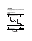
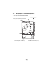
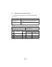
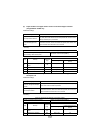
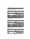
(2) Paper misfeed in the Second image transfer section
<Detection timing>
<Remedy>
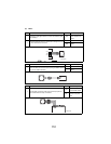
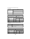
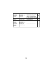
(3) Paper misfeed in the fusing section or the paper feed-out section
<Detection timing>
<Remedy>
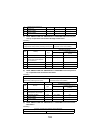
Category Details
Paper misfeed detected in the
Second image transfer section
If PC2 does not pass through when a set amount of time has
passed after the paper interrupts the synchronizing roller sensor
(PC2)
If the light is not interrupted even after the paper has passed the
interruption position for the fusing paper loop detecting sensor
(PC11)
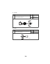
Remaining paper detected in the
Second image transfer section
If the synchronizing roller sensor (PC2) is interrupted when the
machine is turned on, doors and covers are opened, then
closed, and paper misfeeds and malfunctions are corrected
Electrical components for detection of the paper misfeed
Synchronizing roller sensor (PC2)
Fusing paper loop detecting sensor (PC11)
Master board (PWB-A)
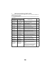
Step Remedy
Reference
page
WARNING DIAGRAM
Control signal
Location(electrical com-
ponent)
1
Perform initial check proce-
dures.
152 - -
2 Check PC2 operation. 149 PC2_ON 5-D
3 Check PC11 operation. 149 PC11_ON 9-B
4 Replace PWB-A. - - -
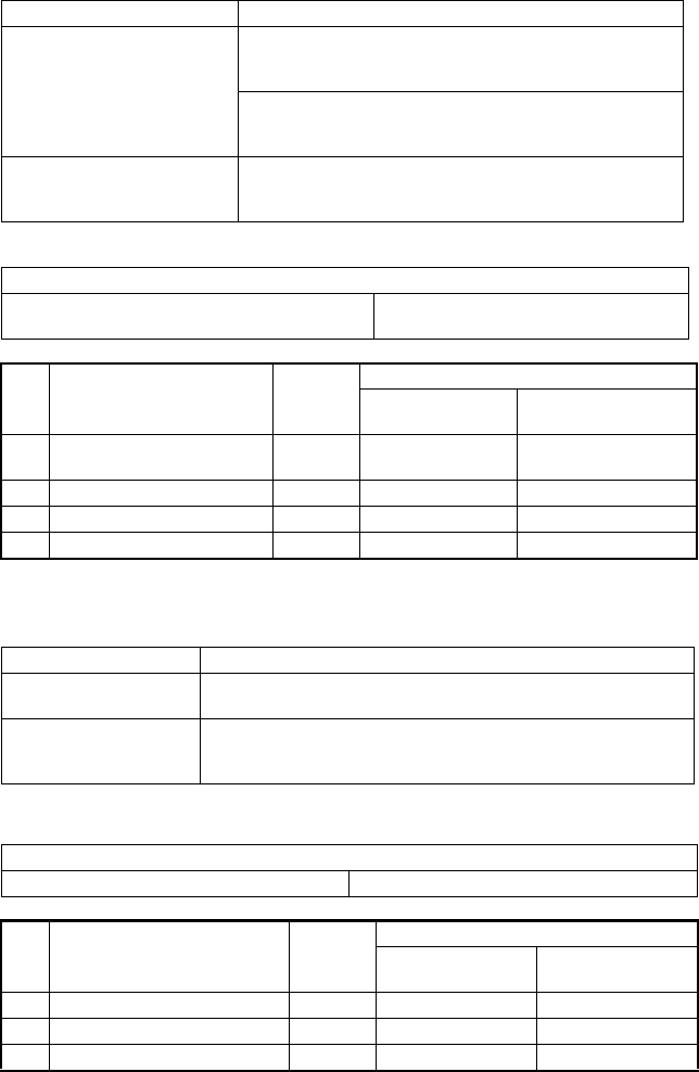
Category Details
Paper misfeed detected in
the paper feed-out section
If PC10 does not pass through when a set amount of time has passed
after the paper interrupts the exit sensor (PC10)
Remaining paper detected
in the paper feed-out sec-
tion
If the exit sensor (PC10) is interrupted when the machine is turned on,
doors and covers are opened, then closed, and paper misfeeds and
malfunctions are corrected
Electrical components for detection of the paper misfeed
Exit sensor (PC10) Master board (PWB-A)
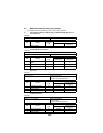
Step Remedy
Reference
page
WARNING DIAGRAM
Control signal
Location(electrical
component)
1 Perform initial check procedures. 152 - -
2 Check PC10 operation. 149 PC10_ON 3-D
3 Replace PWB-A. - - -