


Section 6: Using the Printer Interface
100
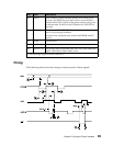
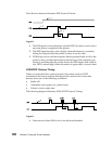
The voltage reference point is the signal ground on pin 7. A timing or control
line is active if the voltage is more than +3 V, or inactive if the voltage is less
than -3 V.
A data signal more than +3 V means that the bit is a logical 0; less than -3 V
means that the bit is a logical 1.
For additional information, refer to the Interface between Data Terminal Equipment
and Data Communications Equipment Employing Serial Binary Data Interchange,
published by the Electronic Industries Association, publications EIA RS-232C
and EIA\TIA-232-E.
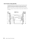
Serial Data Frame Considerations (RS-232C)
The computer sends serial data in data frames (also known as packets). You can
create 10-bit, 11-bit, or 12-bit data frames and set the serial data transfer
parameter so that each data frame contains 7 or 8 data bits. However, the
printer is an 8-bit printer; characters, controls, and APA graphics need 8 bits of
data. If you select 7-bit data transfer, some unexpected characters might print.
Data Transmission
Data transfer rates (in bits per second):
• 300 bps
• 600 bps
• 1200 bps
• 2400 bps
• 4800 bps
• 9600 bps
• 19200 bps
Start and Stop Bits
The printer receives data with 1 start bit and either 1 or 2 stop bits. The printer
always sends 1 start and 2 stop bits.
Parity
There are four possible parity settings: Even, Odd, No, and Ignore.
When Even parity is selected, the printer expects to receive data frames with an
even number of logical 1’s per byte. The printer transmits data with even parity.
When Odd parity is selected, the printer expects to receive data frames with an
odd number of logical 1’s per byte. The printer transmits data with odd parity.