


Section 6: Using the Printer Interface
94
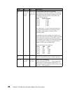
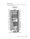
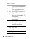
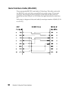
Parallel Pin Assignments
Pin Line Description
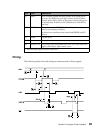
1 STROBE* When the printer receives the STROBE* low from the
computer, the printer reads the data from the interface and
sets the BUSY line high. STROBE* must not occur when the
BUSY line is high; otherwise, unpredictable results may occur.
2-9 DATA These signals are the 8 bits of parallel data sent from the
computer. A high level indicates a logical 1. A low level
indicates a logical 0. The printer reads data from the DATA
lines when a STROBE* pulse is received.
10 ACKNLG* The ACKNLG* pulse tells the computer that the data from the
previous STROBE* pulse has been read. An ACKNLG* pulse
is also generated when the printer is turned on, or at the
completion of the printer initialization by an INIT* requested
from the computer.
11 BUSY When the printer sets BUSY high, it cannot receive data. The
BUSY line goes high in response to a STROBE* pulse. This line
remains high until the data is read. BUSY is also high when:
• The receive buffer is full.
• An out-of-paper condition occurs.
• The printer receives an INIT* signal.
• Start/Stop is pressed to go offline.
• A printer error condition has occurred.
• The printer is initializing.
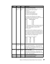
12 PE The printer sets Paper End (PE) high when approximately
12.7 mm (0.5 in.) of paper remains in the printer. PE remains
high until the operator loads paper and presses Start/Stop.
13 SLCT When the printer is ready, it sets the SLCT line high.
The SCLT lines go low when:
• Start/Stop is pressed to go offline.
• There is an error or out-of-paper condition.
• The printer receives an ESC Q. It ignores all incoming data
except DC1, which returns the printer to a select state.
14 AUTO
FEED XT
The printer executes one line feed when this signal,
valid only
in Epson** mode
, is low.
15 Not used.
16 GND Logic ground.
17 CHASSIS
GROUND
Ground level.
18 +5 volts Maximum 300 mA.
19-30 GND Ground level.
* Inverted logic (signal is active when low).