


Diagnostic Information 2-74
4059-XXX
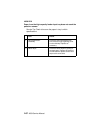
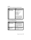
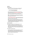
Operator Panel Service Check
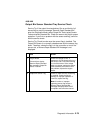
Operator Panel Buttons Service Check
Note:
Before continuing with this service check do the “Button Test”
on page 3-9 in the diagnostic aids chapter. The operator panel cable
is a individual cable on some printers and a combination cable
assembly with the cover switch cable on later models.
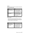
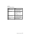
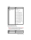
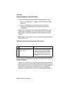
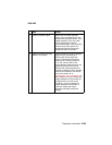
4 Motor does not turn, no
gear error code 936or User
message 201 Paper Jam
displays.
Check the voltages at J12 on the
engine board.
Pin number and voltage:
J12-1 = +24 V dc
J12-4 = +5 V dc (static) 0 V dc
(when main drive motor running)
J12-5 = + 5 V dc (static) 0 V dc
(when main drive motor running)
J12-6 = +5 V dc (static) +2.5 V dc
(when main drive motor running)
J12-7 = +5 V dc (static) 0 V dc
(when main drive motor running)
J12-8 = +5 V dc (static) +5 V dc
(when main drive motor running)
J12-11 = + 5 V dc (static) 0 V dc
(when main drive motor running)
If the voltage is incorrect,replace the
FRUs in the following order:
main drive motor assembly
engine board
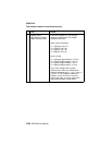
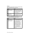
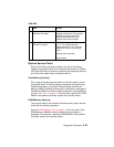
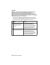
FRU Action
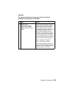
1 Operator Panel Assembly If any button fails the Button Test,
replace the operator panel assembly.
FRU Action