


4-7 4059 Service Manual
4059-XXX
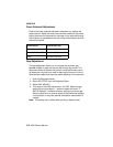
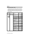
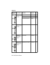
Screw Identification Table
The following table contains screw types, locations, and quantities
necessary to service the printer. Each screw callout in the removal
procedure graphic displays the screw reference number listed in the
table. Pay careful attention to each screw type location when doing
removals. You must install the correct screw type in each location
during reassembly.
Reference
Number
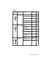
Screw Type Location Purpose Qty
M3.5x8 mm
Thread Cutting
right side frame to
center pan
attach 1
toner level sensor mounting 1
charge roll mounting 1
main drive gearbox mounting 3
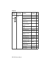
EP module to left and
right side frame
attach 9
developer drive
assembly
mounting 2
left side cover gap to left
frame
attach 2
stacker duct to frame mounting 2
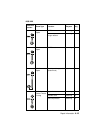
cartridge hold down
assembly
mounting 2
MPT deflector mounting 2
fuser to frame mounting 2
interconnect board
shield ground
attach 2
engine board shield to
frame
attach 1
laser cover mounting 5