


Diagnostic Information 2-52
4059-XXX
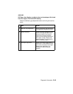
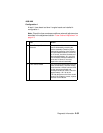
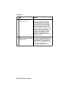
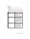
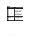
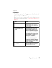
Configuration 1
A level 1 fuser board and level 1 engine board are installed in
configuration 1.
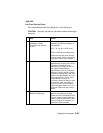
Note: Check the fuser envelope conditioner solenoid adjustment as
described in the adjustment section “Fuser Solenoid Adjustment” on
page 4-3.
FRU Action
1 Fuser Envelope Conditioner
Solenoid
The operation of the fuser solenoid
can be observed by removing the
redrive assembly. Check for proper
mechanical operation of the solenoid
and associated hardware, link and so
on. If correct, check the resistance of
the solenoid between J4-1 and J4-2.
The resistance measures between 5
ohms and 10 ohms. If incorrect,
replace the solenoid assembly.
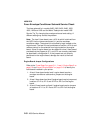
2 Fuser Control Board The solenoid receives power from the
fuser control board. The fuser control
board receives +42Vdc from the LVPS
via the interconnect board and
envelope conditioner cable. Check for
approximately +42 V dc at the
+42 V dc testpoint on the fuser control
board. If the voltage is correct, replace
the fuser control board.