


2-63 4059 Service Manual
4059-XXX
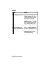
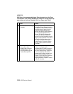
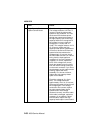
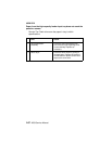
5 High Capacity Feeder
Option Control Board
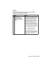
Check the voltage on J8-1 (green).
The voltage measures +24 V dc. If
incorrect, check the autoconnect
system for any problems. +24 V dc
must come from the base printer
through the autoconnect system to
the high capacity input for the high
capacity feeder to be recognized. If
the voltage is correct, check the
voltages at J11-3(red) and J11-
4(red). The voltages measure +24 V
dc. If correct, replace the high
capacity feeder optionsystem board.
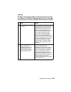
If incorrect, disconnect J8 from the
system board and measure the
voltages again. If incorrect, check
the LVPS cable and the A.C. internal
wiring from the input appliance
receptacle. If incorrect, replace as
necessary. If correct, replace the
LVPS. If the voltages are correct,
check the stepper motor for shorts
from the motor housing to each pin
on the motor connector. If you find a
short between any pin and the motor
housing, replace the motor
assembly. If no shorts are found,
replace the high capacity feeder
option control board.
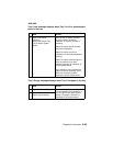
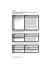
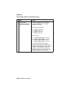
Check the voltage at J9-1 (light
blue). The voltage measures
approximately +24 V dc. If incorrect,
disconnect the cable atJ9 and check
the voltage again. If the voltage
continues to be incorrect, replace
the high capacity feeder option
system board. If the voltage
measures correctly, check the cable.
If the cable is damaged, replace as
necessary. If no problem is found
with the cable, replace the high
capacity feeder option control board.
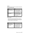
FRU Action