


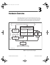

Chapter 1 Introduction
PCI-4451/4452 User Manual 1-4
©
National Instruments Corporation
application you can use to make measurements as you would with a
standard dynamic analyzer.
ComponentWorks contains tools for data acquisition and instrument
control built on NI-DAQ driver software. ComponentWorks provides a
higher-level programming interface for building virtual instruments with
Visual Basic, Visual C++, Borland Delphi, and Microsoft Internet Explorer.
With ComponentWorks, you can use all of the configuration tools, resource
management utilities, and interactive control utilities included in NI-DAQ.
Measure is a data acquisition and instrument control add-in for Microsoft
Excel. With Measure, you can acquire data directly from plug-in DAQ
boards, GPIB instruments, or serial (RS-232) devices. Measure has
easy-to-use dialogs for configuring your measurements. Your data is placed
directly into Excel worksheet cells, from which you can perform your
analysis and report generations using the full power and flexibility of Excel.
Optional Equipment
National Instruments offers a variety of products to use with your
PCI-4451/4452 series devices, including cables and connector blocks as
follows:
•
SHC50-68 digital cable
•
Shielded and DIN rail mountable 68-pin connector blocks
•
RTSI cables
Custom Cabling
National Instruments offers cables of different lengths and the BNC-2140
DSA accessory to connect your analog I/O to the PCI-4451/4452. National
Instruments recommends you do not develop your own cabling solution
due to the difficulty of working with the high-density connector and the
need to maintain high signal integrity. However, if your application
requires that you develop your own cable use the following guidelines:
• Use shielded twisted-pair wires for each differential analog input or
output channel pair. Since the signals are differential, using this type
of wire yields the best results.
• When connecting the cable shields, be sure to connect the analog input
grounds to the AIGND pins and the analog output grounds to the
AOGND pins. For a connector pin assignment, refer to Table 4-1,
Analog I/O Connector Pin Assignment.
User.book Page 4 Tuesday, April 14, 1998 10:20 AM