


Chapter 4 Signal Connections
©
National Instruments Corporation 4-15 PCI-4451/4452 User Manual
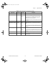
As an input, you can individually configure each PFI for edge or level
detection and for polarity selection as well. You can use the polarity
selection for any of the timing signals, but the edge or level detection
depends upon the particular timing signal being controlled. The detection
requirements for each timing signal are listed within the section that
discusses that individual signal.
In edge-detection mode, the minimum pulse width required is 10 ns. This
applies for both rising-edge and falling-edge polarity settings. There is no
maximum pulse-width requirement in edge-detect mode.
In level-detection mode, there are no minimum or maximum pulse-width
requirements imposed by the PFIs themselves, but there can be limits
imposed by the particular timing signal being controlled. These
requirements are listed later in this chapter.
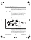
Acquisition Timing Connections
The acquisition timing signals are PFI0/TRIG1, PFI1/TRIG2,
CONVERT*, and EXTSTROBE*.
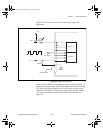
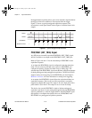
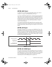
Posttriggered data acquisition allows you to view only data that is acquired
after a trigger event is received. A typical posttriggered acquisition
sequence is shown in Figure 4-6.
Figure 4-6.
Typical Posttriggered Acquisition
13042
TRIG1
CONVERT*
Scan Counter
User.book Page 15 Tuesday, April 14, 1998 10:20 AM