


Chapter 4 Signal Connections
PCI-4451/4452 User Manual 4-14
©
National Instruments Corporation
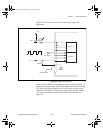
Digital Power Connections
Four pins on the digital I/O connector supply +5 V from the computer
power supply via a self-resetting fuse. The fuse will reset automatically
within a few seconds after the overcurrent condition is removed. These pins
are referenced to DGND and you can use them to power external digital
circuitry.
• Power rating +4.65 to +5.25 VDC at 1 A
Caution
Do not under any circumstances connect these +5 V power pins directly to analog
ground, digital ground, or to any other voltage source on the PCI-4451/4452
device or any other device. Doing so can damage the PCI-4451/4452 device and
the computer. National Instruments is not liable for damages resulting from such
a connection.
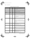
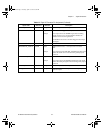
Timing Connections
All external control over the timing of your PCI-4451/4452 device is routed
through the 10 programmable function inputs labeled PFI0 through PFI9
(excluding PFI2 and PFI5). These signals are explained in detail in the next
section, Programmable Function Input Connections. Most of these PFIs
are bidirectional. As outputs they are not programmable and reflect the
state of acquisition, waveform generation, and general-purpose timing
signals. As inputs, the PFI signals are programmable and can control any
acquisition, waveform generation, and general-purpose timing signals.
The acquisition signals are explained in the Acquisition Timing
Connections section later in this chapter. The waveform generation signals
are explained in the Waveform Generation Timing Connections section
later in this chapter. The general-purpose timing signals are explained in the
General-Purpose Timing Signal Connections section later in this chapter.
All digital timing connections are referenced to DGND.
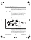
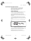
Programmable Function Input Connections
You can individually enable each of the PFI pins to output a specific
internal timing signal. For example, if you need the GPCTR1_SOURCE
signal as an output on the I/O connector, software can turn on the output
driver for the PFI3/GPCTR1_SOURCE pin.
Caution
Be careful not to drive a PFI signal externally when it is configured as an output.
!
!
User.book Page 14 Tuesday, April 14, 1998 10:20 AM