


Chapter 4 Signal Connections
PCI-4451/4452 User Manual 4-18
©
National Instruments Corporation
EXTSTROBE* Signal
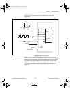
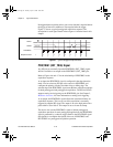
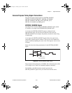
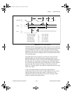
EXTSTROBE* is an output-only signal that generates either a single pulse
or a sequence of eight pulses in the hardware-strobe mode. An external
device can use this signal to latch signals or to trigger events. In
single-pulse mode, software controls the level of the EXTSTROBE*
signal. A 10 µs and a 1.2 µs clock is available for generating a sequence
of eight pulses in hardware-strobe mode. Figure 4-8 shows the timing for
hardware-strobe mode EXTSTROBE* signal.
Figure 4-8.
EXTSTROBE* Signal Timing
Waveform Generation Timing Connections
The waveform generation timing signals are WFTRIG and UPDATE*.
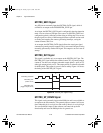
WFTRIG Signal
Any PFI pin can externally input the WFTRIG signal, which is available as
an output on the PFI6/WFTRIG pin.
As an input, the WFTRIG signal is configured in the edge-detection mode.
You can select any PFI pin as the source for WFTRIG and configure the
polarity selection for either rising or falling edge. The selected edge of the
WFTRIG signal starts the waveform generation for the DACs.
As an output, the WFTRIG signal reflects the trigger that initiates
waveform generation. This is true even if the waveform generation is
externally triggered by another PFI signal. The output is an active high
pulse with a pulse width of 50 to 100 ns. This output is set to tri-state at
startup.
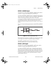
UPDATE* Signal
The UPDATE* signal is only available as an output on the UPDATE* pin.
The UPDATE* signal reflects the end of a delta-sigma conversion on the
DACs. The output is an active-low pulse with a pulse width of 70 to 100 ns.
This output is set to tri-state at startup.
t
w
t
w
V
OH
V
OL
t
w
= 600 ns or 5 µs
User.book Page 18 Tuesday, April 14, 1998 10:20 AM