


Chapter 3 Hardware Overview
PCI-4451/4452 User Manual 3-10
©
National Instruments Corporation
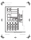
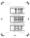
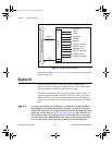
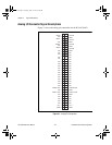
Figure 3-8.
RTSI Bus Signal Connection
Refer to the Chapter 4, Signal Connections for a description of the signals
shown in Figure 3-8.
Digital I/O
The PCI-4451/4452 devices contain eight lines of digital I/O for
general-purpose use through the 50-pin connector. You can individually
software-configure each line for either input or output.
The hardware up/down control for general-purpose counters 0 and 1 are
connected onboard to DIO6 and DIO7, respectively. Thus, you can use
DIO6 and DIO7 to control the general-purpose counters. The up/down
control signals are input only and do not affect the operation of the DIO
lines.
Note At system power-on and reset, the hardware sets both the PFI and DIO lines to
high impedance. This means that the device circuitry is not actively driving the
output either high or low. For example, DIO(0) will be in the high impedance state
after power on, and Table 4-4, Digital I/O Signal Summary, shows that there is a
50 kΩ pull-up resistor. This pull-up resistor sets the DIO(0) pin to a logic high
when the output is in a high-impedance state. Take careful consideration of the
power-on state of the system to prevent any damage to external equipment.
RTSI Bus Connector
switch
RTSI Switch
Clock
Trigger 7
DAQ-STC
TRIG1
TRIG2
CONVERT*
UPDATE*
WFTRIG
GPCTR0_SOURCE
GPCTR0_GATE
GPCTR0_OUT
GPCTR1_SOURCE
GPCTR1_GATE
RTSI_OSC (20 MHz)
User.book Page 10 Tuesday, April 14, 1998 10:20 AM