


©
National Instruments Corporation 4-1 PCI-4451/4452 User Manual
4
Signal Connections
This chapter describes how to make input and output connections to your
PCI-4451/4452 device via the analog I/O and digital I/O connectors of the
device.
The analog I/O connector for the PCI-4451/4452 connects to the
BNC-2140 DSA accessory through the SHC68-C68-A1 shielded cable.
You can access the analog I/O of the PCI-4451/4452 using standard BNC
connectors on the BNC-2140. You can connect the analog I/O signals to the
shielded cable through a single 68-pin connector.
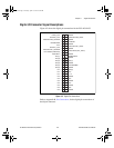
The digital I/O connector for the PCI-4451/4452 has 50 pins that you can
connect to generic 68-pin terminal blocks through the SHC50-68 shielded
cable. You can connect the digital I/O signals to the shielded cable through
a single 50-pin connector.
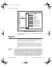
I/O Connectors
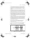
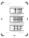
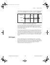
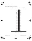
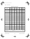
Table 4-1 describes the pin assignments for the 68-pin analog I/O
connector. Table 4-3 describes the 50-pin digital connector on the
PCI-4451/4452 devices. A signal description follows the connector
pinouts.
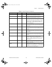
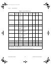
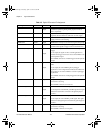
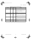
Caution
Connections that exceed any of the maximum ratings of input or output signals
on the PCI-4451/4452 devices can damage the PCI-4451/4452 device, the
computer, and associated accessories. Maximum input ratings for each signal are
given in the Protection column of Table 4-2 and 4-4. National Instruments is not
liable for any damages resulting from such signal connections.
!
User.book Page 1 Tuesday, April 14, 1998 10:20 AM