


Chapter 4 Signal Connections
PCI-4451/4452 User Manual 4-6
©
National Instruments Corporation
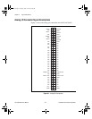
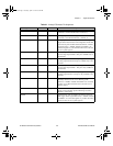
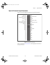
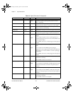
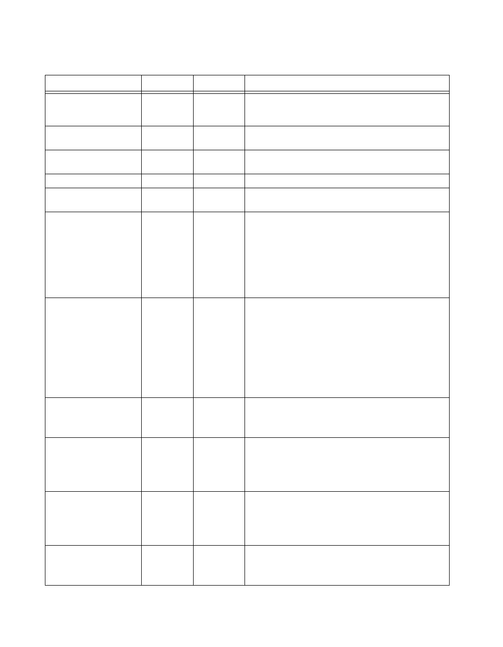
Table 4-3.
Digital I/O Connector Pin Assignment
Signal Name Reference Direction Description
DIO<0..7> DGND Input or
Output
Digital I/O channels 0 through 7—Channels 6 and 7 can
control the up/down signal of general-purpose counters 0
and 1, respectively.
DGND — — Digital Ground—This pin supplies the reference for the digital
signals at the I/O connector as well as the +5 VDC supply.
+5 V DGND Output +5 VDC Source—These pins are fused for up to 1 A of +5 V
supply. The fuse is self-resetting.
RESERVED1 DGND Output RESERVED—This pin is reserved. This signal is always high.
EXTSTROBE* DGND Output External Strobe—This signal can be toggled under software
control to latch signals or trigger events on external devices.
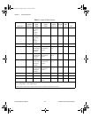
PFI0/TRIG1 (EXT_TRIG) DGND Input
Output
TRIG1—As an input, this is a source for the data acquisition
trigger.
As an output, this signal can drive external applications to
indicate that a trigger on the device has occurred. TRIG1 is the
start acquisition signal.
In LabVIEW, referred to as AI Start Trigger for both input and
output.
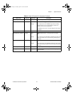
PFI1/TRIG2 (PRETRIG) DGND Input
Output
PFI1/TRIG2 (PRETRIG)—As an input, this is one of the
PFIs.
As an output, this is the TRIG2 signal. In pretrigger
applications, a low-to-high transition indicates the initiation of
the posttrigger conversions. TRIG2 is not used in posttrigger
applications.
In LabVIEW, referred to as AI Stop Trigger for both input and
output.
CONVERT* DGND Output A high-to-low edge on CONVERT* indicates that an A/D
conversion is occurring.
In LabVIEW, referred to as AI Convert.
PFI3/GPCTR1_SOURCE DGND Input
Output
PFI3/Counter 1 Source—As an input, this is one of the PFIs.
As an output, this is the GPCTR1_SOURCE signal. This signal
reflects the actual source connected to the general-purpose
counter 1.
PFI4/GPCTR1_GATE DGND Input
Output
PFI4/Counter 1 Gate—As an input, this is one of the PFIs.
As an output, this is the GPCTR1_GATE signal. This signal
reflects the actual gate signal connected to the general-purpose
counter 1.
UPDATE* DGND Output A high-to-low edge on UPDATE* indicates that a D/A
conversion is occurring.
In LabVIEW, referred to as AO Update.
User.book Page 6 Tuesday, April 14, 1998 10:20 AM