


Chapter 6 Theory of Analog Operation
PCI-4451/4452 User Manual 6-10
©
National Instruments Corporation
Analog Output Circuitry
The PCI-4451 has two analog output channels, either of which is illustrated
in Figure 4-4, Analog Output Channel Block Diagram.
A common application for the analog output is to stimulate a system under
test while measuring the response with the analog inputs. The input and
output sample clocks are synchronized and derived from the same DDS
clock. The input and output clocks can differ from each other by a factor of
2 (1, 2, 4, 8, ... 128) while still maintaining their synchronization. Output
conversions occur simultaneously at software-programmable rates from
1.25 to 51.2 kS/s, in increments of 47.684 µS/s.
The analog output circuitry uses eight-times oversampling interpolators
with 64-times oversampling delta-sigma modulators to generate
high-quality signals. The output channel has a range up to ±10 V
(7.07 V
rms
) and can be driven as SE or DIFF. The analog output also has an
attenuation stage so you can choose attenuation of 0, −20, or −40 dB.
Because of the delta-sigma modulating DAC, the device is immune to DNL
distortion. The analog output stage generates signals with extremely low
noise and low distortion. Because the device has a 93 dB dynamic range, it
is possible to generate low-noise waveforms. The device also has excellent
amplitude flatness of ±0.2 dB within the frequency range of DC to 23 kHz
and has a total harmonic distortion (THD) of −95 dB at 1 kHz. With these
specifications, you are assured of the quality and integrity of the output
signals generated.
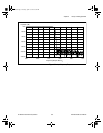
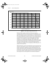
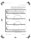
Anti-Image Filtering
A sampled signal repeats itself throughout the frequency spectrum. These
repetitions begin above one-half the sample rate (F
s
) and, at least in theory,
continue up through the spectrum to infinity, as shown in Figure 6-5a.
Because the sample data actually represents only the frequency
components below one-half the sample rate (the baseband), it is desirable
to filter out all these extra images of the signal. The PCI-4451 accomplishes
this filtering in two stages.
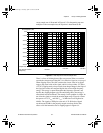
First, the
data is digitally resampled at eight times the original sample rate.
Then, a linear-phase digital filter removes almost all energy above one-half
the original sample rate and sends the data at the eight-times rate to the
DAC, as shown in Figure 6-5b. Some further (inherent) filtering occurs at
the DAC because the data is digitally sampled and held at eight times the
sample rate. This filtering has a sin x / x response, yielding nulls at multiples
User.book Page 10 Tuesday, April 14, 1998 10:20 AM