


Chapter 4 Signal Connections
©
National Instruments Corporation 4-7 PCI-4451/4452 User Manual
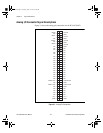
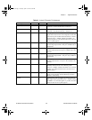
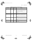
GPCTR1_OUT DGND Output General-Purpose Counter 1 Output
PFI6/WFTRIG DGND Input
Output
PFI6/Waveform Trigger—As an input, this is one of the PFIs.
As an output, this is the WFTRIG signal. In timed analog
output sequences, a low-to-high transition indicates the
initiation of the waveform generation.
In LabVIEW, referred to as AO Start Trigger for both input
and output.
PFI7 DGND Input PFI7—This is one of the PFIs.
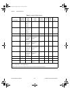
PFI8/GPCTR0_SOURCE DGND Input
Output
PFI8/Counter 0 Source—As an input, this is one of the
PFIs.
As an output, this is the GPCTR0_SOURCE signal. This signal
reflects the actual source connected to the general-purpose
counter 0.
PFI9/GPCTR0_GATE DGND Input
Output
PFI9/Counter 0 Gate—As an input, this is one of the PFIs.
As an output, this is the GPCTR0_GATE signal. This signal
reflects the actual gate signal connected to the general-purpose
counter 0.
GPCTR0_OUT DGND Output General-Purpose Counter 0 Output
FREQ_OUT DGND Output Frequency Output—This output is from the frequency
generator output.
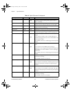
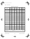
Table 4-3.
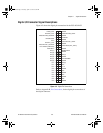
Digital I/O Connector Pin Assignment (Continued)
Signal Name Reference Direction Description
User.book Page 7 Tuesday, April 14, 1998 10:20 AM