


Chapter 3 Hardware Overview
©
National Instruments Corporation 3-9 PCI-4451/4452 User Manual
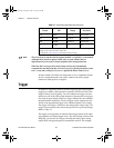
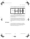
In low-hysteresis triggering mode, the trigger is generated when the signal
value is less than lowValue, with the hysteresis specified by highValue.
Figure 3-7.
Low-Hysteresis Triggering Mode
You can use digital triggering through the RTSI bus and the external digital
50-pin connector using any one of the eight available programmable
function input (PFI) pins. PFI0/TRIG1 (EXT_TRIG) is the pin dedicated to
external digital triggering.
You can trigger the PCI-DSA devices from any other PCI-DSA device or
any National Instruments device that has the RTSI bus feature. You can
connect the devices through the RTSI bus cable. An external digital trigger
can also trigger multiple devices simultaneously by distributing that trigger
through the RTSI bus. You can select the polarity of the external digital
trigger.
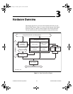
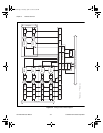
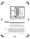
RTSI Triggers
The seven RTSI trigger lines on the RTSI bus provide a very flexible
interconnection scheme for any PCI-4451/4452 device sharing the RTSI
bus. These bidirectional lines can drive any of eight timing signals onto the
RTSI bus and can receive any of these timing signals. This signal
connection scheme is shown in Figure 3-8.
highValue
Trigger
lowValue
User.book Page 9 Tuesday, April 14, 1998 10:20 AM