


Chapter 3 Hardware Overview
©
National Instruments Corporation 3-3 PCI-4451/4452 User Manual
Analog Input
The analog input section of each PCI-4451/4452 device is software
configurable. You can select different analog input configurations through
application software. The following sections describe in detail each of the
analog input categories.
Input Mode
The PCI-4451/4452 devices use differential (DIFF) inputs. You can
configure the input as a referenced single ended (SE) channel using the
BNC-2140 DSA accessory. For more information, please refer to the
BNC-2140 User Manual. In DIFF mode, one line connects to the positive
input of the channel, and the other connects to the negative input of the
same channel. You can connect the differential input to SE or DIFF signals,
either floating or ground-referenced. However, grounding the negative
input from floating sources may improve the measurement quality by
removing the common-mode noise.
Input Coupling
The PCI-4451/4452 has a software-programmable switch that determines
whether a capacitor is placed in the signal path. If the switch is set for DC,
the capacitor is bypassed and any DC offset present in the source signal is
passed to the ADC. If the source has a significant amount of unwanted
offset (bias voltage), you must set the switch for AC coupling to place the
capacitor in the signal path and take full advantage of the input signal
range.
Input Polarity and Input Range
The PCI-4451/4452 devices operate in bipolar mode. Bipolar input
means that the input voltage range is between –V
ref
/2 and +V
ref
/2.
The PCI-4451/4452 has a bipolar input range of 20 V (±10 V) for a
gain of 1.0 (0 dB).
You can program the range settings on a per channel basis so that you can
configure each input channel uniquely. The software-programmable gain
on these devices increases their overall flexibility by matching the input
signal ranges to those that the ADC can accommodate. With the proper gain
setting, you can use the full resolution of the ADC to measure the input
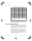
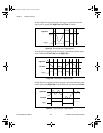
signal. Table 3-1 shows the overall input range and precision according to
the input range configuration and gain used.
User.book Page 3 Tuesday, April 14, 1998 10:20 AM