


Chapter 3 Hardware Overview
©
National Instruments Corporation 3-7 PCI-4451/4452 User Manual
you can configure the analog input section to acquire a given number of
samples after the analog input signal crosses a specific threshold. As
another example, you can configure the analog output section to generate
an output waveform whenever the analog input signal crosses a specific
threshold.
Due to the nature of delta-sigma converters, the triggering circuits operate
on the digital output of the converter. Since the trigger is generated at the
output of the converter, triggers can occur only when a sample is actually
generated. Placing the triggering circuits on the digital side of the converter
does not affect most measurements unless an analog output is generated
based on the input trigger. In this case, you must be aware of the inherent
delays of the finite impulse response (FIR) filters internal to the delta-sigma
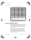
converters and you must account for the delays. The delay through the input
converter is 42 sample periods, while the delay through the output converter
is 34.6 ±0.5 sample periods.
During repetitive sampling of a waveform, you may observe jitter due to the
uncertainty of where a trigger level falls compared to the actual digitized
data. Although this trigger jitter is never greater than one sample period, it
can seem quite bad when the sample rate is only twice the bandwidth of
interest. This jitter has no effect on the processing of the data, and you can
decrease this jitter by oversampling.
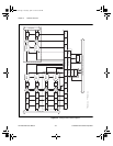
There are five analog level triggering modes available, as shown in
Figures 3-3 through 3-7. You can set lowValue and highValue
independently in the software.
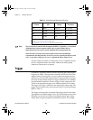
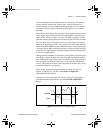
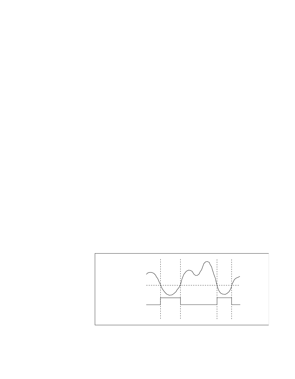
In below-low-level triggering mode, shown in Figure 3-3, the trigger is
generated when the signal value is less than lowValue. HighValue is
unused.
Figure 3-3.
Below-Low-Level Triggering Mode
lowValue
Trigger
User.book Page 7 Tuesday, April 14, 1998 10:20 AM