


Chapter 4 Signal Connections
PCI-4451/4452 User Manual 4-22
©
National Instruments Corporation
As an output, the GPCTR1_GATE signal monitors the actual gate signal
connected to general-purpose counter 1. This is true even if the gate is
externally generated by another PFI signal. This output is set to tri-state at
startup.
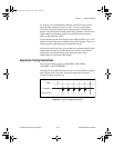
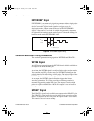
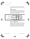
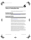
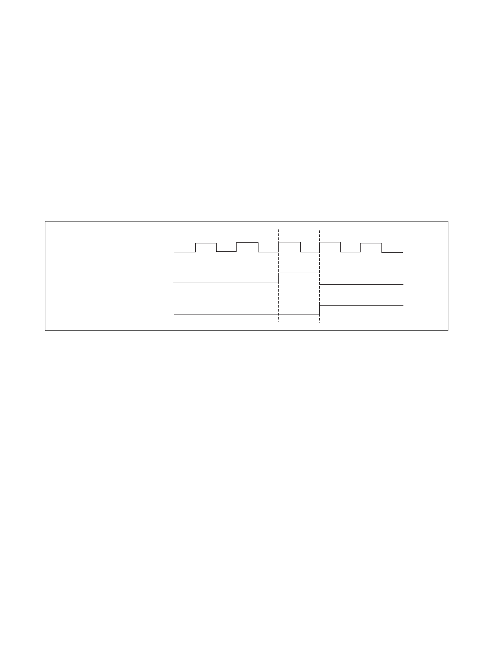
GPCTR1_OUT Signal
This signal is available only as an output on the GPCTR1_OUT pin. The
GPCTR1_OUT signal monitors the TC device general-purpose counter 1.
You have two software-selectable output options—pulse on TC and toggle
output polarity on TC. The output polarity is software selectable for both
options. This output is set to tri-state at startup. Figure 4-12 shows the
timing requirements for the GPCTR1_OUT signal.
Figure 4-12.
GPCTR1_OUT Signal Timing
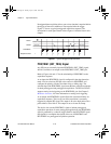
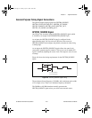
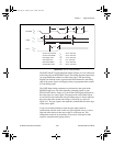
GPCTR1_UP_DOWN Signal
This signal can be externally input on the DIO7 pin and is not available as
an output on the I/O connector. General-purpose counter 1 counts down
when this pin is at a logic low and counts up at a logic high. This input can
be disabled so that software can control the up-down functionality and
leave the DIO7 pin free for general use. Figure 4-13
shows the timing
requirements for the GATE and SOURCE input signals and the timing
specifications for the OUT output signals of your PCI-4451/4452 device.
GPCTR1_SOURCE
GPCTR1_OUT
GPCTR1_OUT
(Toggle output on TC)
(Pulse on TC)
TC
User.book Page 22 Tuesday, April 14, 1998 10:20 AM