


Section Two Configuration and Installation
© National Instruments Corporation 2-3 GPIB-COM User Manual
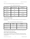
Table 2-1 shows the standard base I/O address and interrupt level for each serial port.
Table 2-1. IBM PC Serial Port Adapters
Name of Port Base I/O Address (hex) Interrupt Level
Serial Port 1 3F8 4
Serial Port 2 2F8 3
Serial Port 3 3E8 Not Used
Serial Port 4 2E8 Not Used
Switch and Jumper Settings
Table 2-2 shows the factory settings and optional configurations for the switches and jumpers on
the GPIB-COM.
Table 2-2. Factory Default Settings and Optional Configurations
GPIB-COM Default Optional
Base I/O Address 3F8 2F8, 3E8, 2E8
Interrupt Level 4 3
If you need to change the factory settings, continue on. If you do not need to change the factory
settings, skip to Installation later in this section.
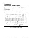
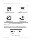
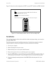
Base I/O Address and Interrupt Selection
The base I/O address and interrupt line used by the GPIB-COM are determined by the jumpers
located at positions W2 and W5. The jumpers are set at the factory for base I/O address 3F8 hex
and interrupt level 4.