


Section Two Configuration and Installation
© National Instruments Corporation 2-7 GPIB-COM User Manual
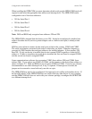
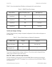
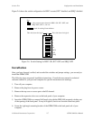
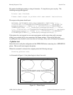
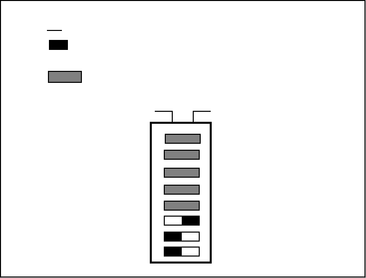
Figure 2-6 shows the switch configuration for REN* asserted, IFC* disabled, and SRQ* disabled.
Key
= side you must press down for REN* ON, IFC* OFF, and
SRQ* OFF; Off = 1; On = 0.
This side down for logic 1 This side down for logic 0
U13
= used for setting Listen Address
1
2
4
8
16
REN
IFC
SRQ
12 3 45 678
OFF
Figure 2-6. Switch Setting for REN* ON, IFC* OFF, and SRQ* OFF
Installation
Once you have changed, verified, and recorded the switches and jumper settings, you are ready to
install the GPIB-COM.
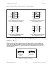
The following steps are general installation instructions. Consult the user manual or technical
reference manual of your personal computer for specific instructions and warnings.
1. Turn off your computer.
2. Remove the plug from its power source.
3. Remove the top cover or access port to the I/O channel.
4. Remove the expansion slot cover on the back panel of your computer.
5. Insert the GPIB-COM in an unused full-length slot with the IEEE-488 receptacle sticking out
of the opening of the back panel. It may be a tight fit, but do not force the board into place.
6. Screw the right angle mounting bracket of the GPIB-COM to the back panel rail of your
computer.